GB
INSTRUCTION MANUAL
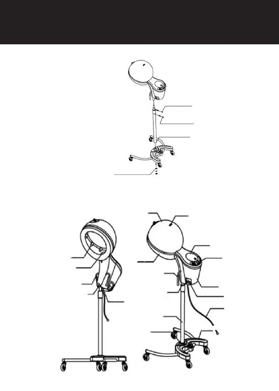
MOUNTING INSTRUCTION
IDENTIFICATION OF PARTS
Fig. 1
Fig. 2
Infrared radiator
Nozzle base
Handrail
Connector
ON/OFF switch
Helmet
Rating plate
Cover handle
Rotary cover
Control panel
Handrail
Extensible pipe
Equipment body
Return water container
Return water container
Base pipe housing
Base pipe
Third step: Insert the body of the
equipment into the extension pipe
and tighten the screw
Fifth step: Remove the protective
film from the display
Second step: Tighten up the ring
and the nut
Fourth step:
Remove the locking screw
First step: Adjust the footplate ptotrusion to the
support pipe indentation and fix