2 SRD991 QG EVE0105 B-(en)
MOUNTING TO LINEAR ACTUATORS
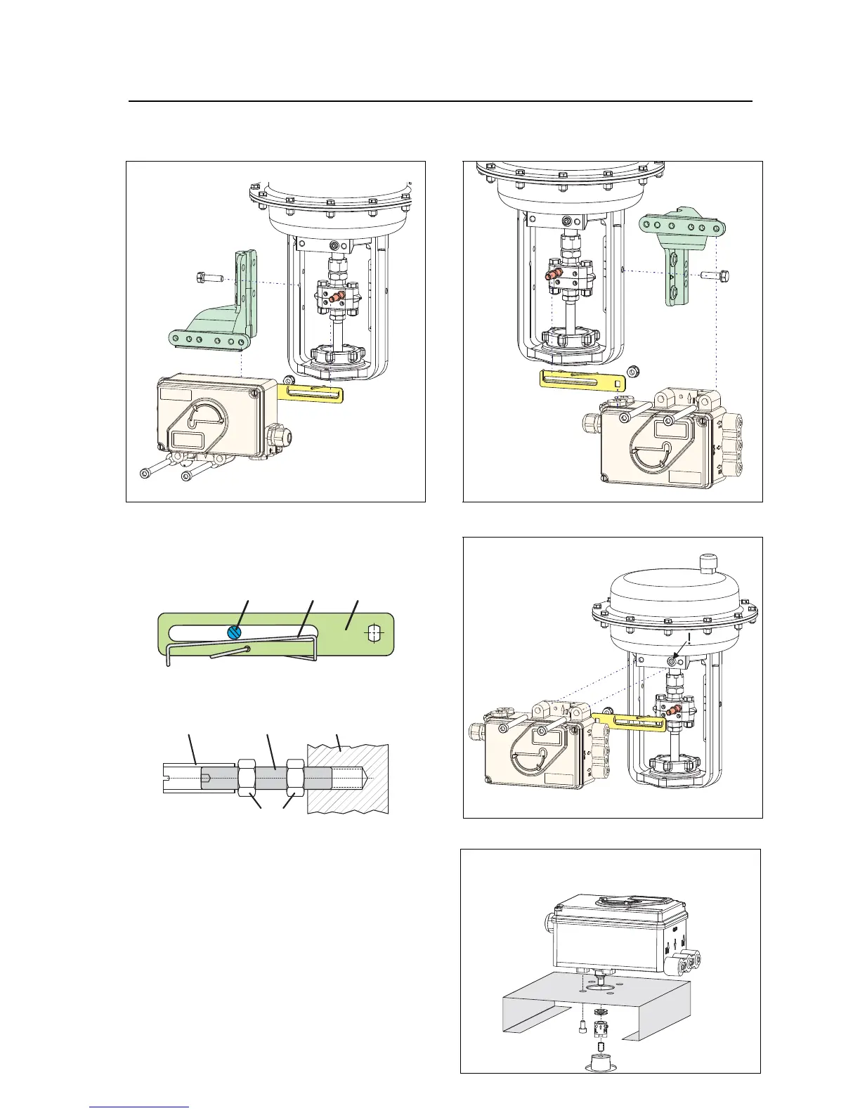
NAMUR Mounting - left hand -
NAMUR Mounting - right hand -
Feedback lever for linear actuators :
Direct Mounting
The carrier bolt B is in the slot of the feedback
lever A and the compensating spring F touches
the carrier bolt.
)* .
Carrier bolt B:
1 threaded sleeve 2 Stud 3 coupling piece
M 6
1 2 3
MOUNTING TO ROTARY ACTUATORS
• Do not tighten grub screw 4 against the thread
of spindle 9 !
• When in use the flat side of the spindle 9 must
move ( 0 ↔ 100%) in front of the arrow 26.
• When the product temperature rises, the drive
shaft 1 increases in length. Therefore, the rotary
adapter 3 must be mounted so that approx. 1
mm (0.04 in.) of clearance results between the
drive shaft 1 and the rotary adapter 3. This is
achieved by placing an appropriate number of
washers 5, on the feedback spindle 9, before
attaching the rotary adapter. Two washers
should result in a clearance of 1 mm.
 Loading...