Chapter 1 Product Introduction
4
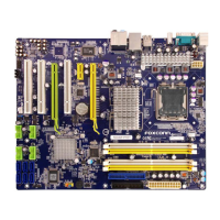
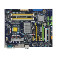
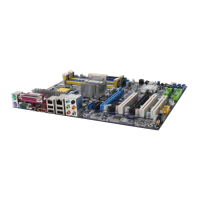
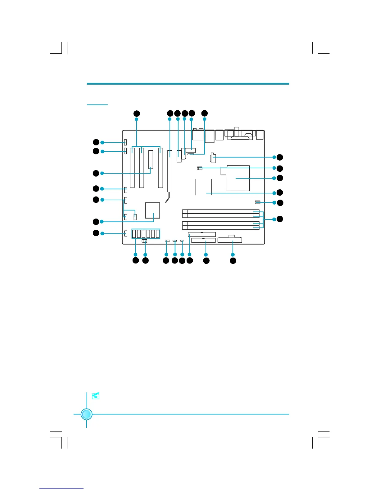
Layout
15.SYS_FAN Connector
16. Speaker Connector (optional)
17. Clear CMOS Jumper
18. Chassis Intruder Connector
19. IDE Connector: PIDE
20. FDD Connector
21. 24-pin ATX Power Connector: PWR1
22. DDR2 DIMM Slots
23. CPU_Fan Connector
24. North Bridge: Intel
®
P965 Chipset
25. LGA 775 CPU Socket
26. FAN1 Connector
27. 8-pin ATX_12V Power Connector: PWR2
1. IrDA Header
2. COM2 Connector (optional)
3. PWR3 Connector
4. PCI Express x1 Slots
5. PCI Express x16 Slots
6. PCI Slots
7. Front Audio Connector
8. CD_IN Connector
9. PCI Express x4 Slots
10. 1394a Connector (optional)
11. Front USB Connectors
12. South Bridge: Intel
®
ICH8/ICH8R Chipset
13. Front Panel Connector
14. SATA II Connector
Note: The above motherboard layout is provided for reference only, please refer
to the physical motherboard.
8
9
10
11
12
13
14
17
18
19
20 21
22
23
26
27
1
7
6
5 4 3
2
15 16
25
24
PDF 文件使用 "pdfFactory" 试用版本创建 www.fineprint.com.cn