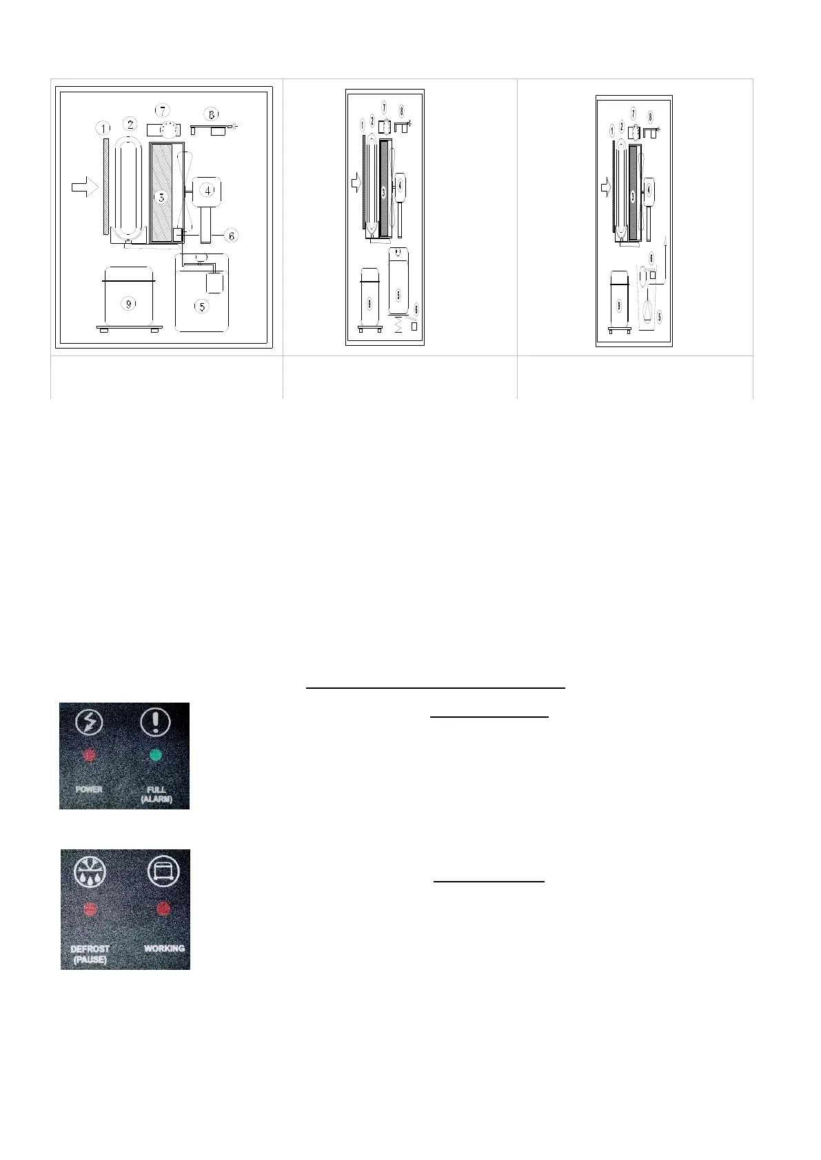
With reference to the drawing (fig. 1), the air is drawn in through the back side of the dehumidifier, then it passes through the
filter (1), through the aluminium refrigerated coil or evaporator (2), again trough the heat- exchanger or condenser (3).
Finally, the motor fan (4) expels the air back into the room through the front grilled panel: The condensed water is collected
in the tank (5). A micro-switch (6) stops the machine when the water in the tank reaches the correct level by raising the
water float lever. The humidistat (7) starts the functioning of the dehumidifier when the humidity his higher than the preset
level. An electronic circuit (8) controls the defrosting and prevents the compressor (9) repeated starts within too short a
time by delaying each new start.
Some models have a different water tank stop device and use a gravity system ( fig. 2) instead of the floating ball.
Fig. 3 refers to the machine provided with lifting pump, which includes a water collection tank (5) and a floating ball stopping
device for full tank (6), in case the pump would not unload properly.
.
Machines provided with Hot Gas Defrosting System
The models with hot gas defrosting system have one by-pass solenoid valve and a special electronic card.
The functioning of Hot Gas Defrosting is an exclusive Fral system for the dehumidifiers: this system consists of a thermostat
and one electronic control, which use the hot gas by-pass system only when it is necessary and for the period of time
required; this will lengthen the life of the machine by reducing the hot gas functioning phases.
.
4. CONTROL AND DISPLAY PANEL
CONTROL PANEL
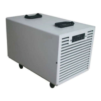
The Control Panel is always placed on the upper side of the machine and consists of 4 lights
indications:
POWER (Supply): red light which turns on when the electric power arrives at the machine;
FULL (ALARM): green light which turns on when the water tank is full, or when the lifting pump is not
working properly and then it fills up the water tank. When this light is on, the machines will stop
running.
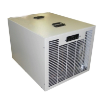
DEFROST: red light which turns on when the compressor is in ‘pause or idle’ position for the
programmed delayed start off at first start up of the machine, or during the defrosting phases.
WORKING (RUNNING): red light on when the dehumidostat starts up automatically the functioning of
the machine.
DEHUMIDOSTAT
May be placed on the front or rear side of the machine.
It consists of a number scale ranging from 1 to 5 or from 1 to 7. The minimum value correspond to
80%, the highest value to 20%; the intermediate value (3-4) indicates that the humidity is at approx.
55%, a suggested good general value.
In the position “CONT”, the machine will keep running all the time, independelntly from the relative
humidity in the room.
In position “OFF”, the machine is not running and will never start running (one-pole switch)
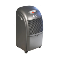
Fig. 1
Machines with water
tank floating ball stop
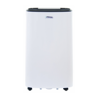
Fig. 2
Machines with water
tank gravity stop
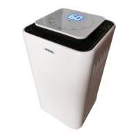
Fig. 3
Machines with condensed
water lifting pump