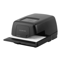
SYSTEM FIGURE REFERENCES
1 Mains connection
2 Fuse holder
3 Mains switch
4 CE conformity symbol
5 Reserve interface
6 9-pole scale interface
7 Nameplate
8 Post lock cover
9 25-pole interface for connecting loading
boxes and PC/laptop
10 Touch-Screen (ComTouch™)
11 Ink ribbon cassette
12 Door lock
13 Letter feed table
14 Table guide
15 Light barrier for letter safety release
16 Light barrier for short letter block
17 Printing mechanism
18 Slit for Short Form Instructions
19 Ink ribbon cassette *
20 Cassette grip *
21 Axle head *
22 Axles *
23 Coil opening *
* See detail drawing, page 13
© All rights reserved. Frama Group.
CONTENTS
Page
21Basic model and options
2 1.1 Basic specifications
2 1.2 Software options
2 1.3 Hardware options
2 1.4 Peripheral options
22Safety instructions /
Accident protection
33Installation /
Mains connection
34Preparing for operation
35Operation
3 5.1 Entering account number
and password
3 5.2 Working menu selection
(sections 5.2.1–5.2.4)
5 5.3 Franking the mail
(sections 5.3.1–5.3.2)
5 5.4 Weight transfer from connected
weighing platform
(sections 5.4.1–5.4.3)
5 5.5 Blocking “High Value”
6 5.6 “ATTN CREDIT” display
6 5.7 No credit loaded
6 5.8 Stamping die switch-on,
switch-off *
(sections 5.8.1–5.8.3)
6 5.9 System settings
(sections 5.9.1–5.9.22)
12 6 Programming ad clichés
12 7 Maintenance
12 7.1 Changing the Colour Cartridge
13 7.2 Option: Rechargeable Thermal Ink
Ribbon Cassette
(sections 7.2.1–7.2.3)
13 7.3 Changing the fuse
13 8 User error messages
15 9 Disposal / Environmental
protection
15 10 Specifications / Accessories
16 11 Conformity declaration
ENGLISH
ESPAÑOLDANSK
SVENSKANORGE
229_Inha_OfficeMail:229_Inha_OfficeMail 30.4.2008 8:58 Uhr Seite 1
Attention!
When franking, the envelope printing
area must be free of hard objects
(paper clips, staples, etc.) that can
mechanically damage the print head.
Frama cannot accept any guarantee
claims or product liability for print
head damage resulting from failure to
observe this operating instruction.