30
REPLACING PARTS
Before performing any maintenance operations, disconnect the appliance from the g a s supply and
electricity network. To replace parts such as knobs and burners, just remove them from the seats
without dis assembling any part of the cooker. To replace parts such as nozzle supports, valves and
electric components follow the procedure described in the burner adjustment paragraph. To replace
the valve or the gas thermostat, it is also necessary to disassemble the two rear gas train brackets,
loosening the 4 screws (2 per bracket) that attach it to the rest of the cooker and, unscrew the nuts
that attach the front burner valves to the control support, after removing all the knobs. To replace the
gas or electric thermostat, also disassemble the rear cooker guard, loosening the relative screws, to
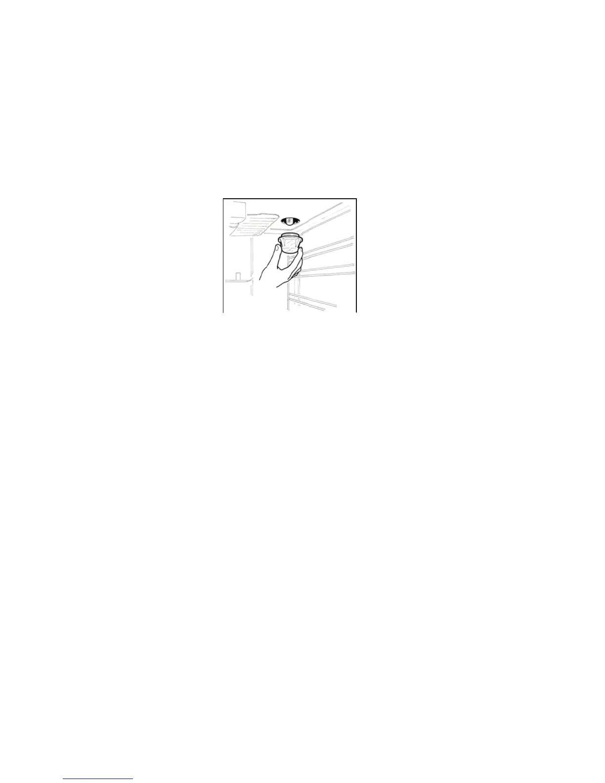
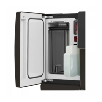
be able to pull down and reposition the thermostat bulb. To replace the oven bulb, just unscrew the
protection cap that projects out inside the oven (Fig.17).
WARNING: Ensure that the appliance is switched off before replacing the lamp to avoid the
possibility of electric shock.
WARNING: The power cord supplied with the appliance is connected to the appliance with an X type
connection (in compliance with standards AS/NZS 60335-1, AS/NZS 60335-2-6 and subsequent
amendments) for which it can be installed without the use of special tools, with the same type of cord
as the one installed.
If the power cord becomes worn or damaged, replace it based on the information reported in table 2.
To replace the power cable, lift the terminal board’s cover and replace the cable.
Chapter 5 Last but not least
Fig.17