EasyManua.ls Logo

Franke KEP AC-EBF-STN Series User Manual

Franke KEP AC-EBF-STN Series
34 pages
To Next Page IconTo Next Page
Page #1 background imageLoading...
Page #1 background image
1
10/17 | 036865-047
INSTALLATION FOR DRINKING FOUNTAIN
COMBINATION OR RETROFIT
For All KEP( )AC(SL)-EBF-SND/STN Series Combination Drinking Fountains
with Electronic Sports Bottle Filler
This HAND-FREE BOTTLE FILLER RETROFIT is an extension of
the Franke drinking fountains product line that mounts directly
above our Universal Drinking Fountain.
The wall requires a standard 2-outlet electrical receptacle to
accommodate the electrical cords from both the fountain and
the bottle filler. Otherwise, a grounded plug-in outlet adapter
will be required.
If installed onto a refrigerated drinking fountain, chilled water
can be dispensed through the Bottle Filler. Otherwise, room
temperature water will be dispensed.
The Bottle Filler is shipped partially assembled.
If you ordered the Bottle Filler as a combination with a Drink-
ing Fountain, the drinking fountain is plumbed and ready to
attach to the bottle filler.
WHEN COMPLETED, THE FINISHED ASSEMBLY WILL LOOK LIKE THIS:
KEP(8)AC-EBF-SND
KEPWEBF
Shown here with the
Sandstone cabinet finish
Question and Answer IconNeed help?

Do you have a question about the Franke KEP AC-EBF-STN Series and is the answer not in the manual?

Franke KEP AC-EBF-STN Series Specifications

General IconGeneral
BrandFranke
ModelKEP AC-EBF-STN Series
CategoryWater Dispenser
LanguageEnglish

Summary

Installation for Drinking Fountain Combination or Retrofit

Section 1: Getting Started

What's Included?

Lists components provided with the bottle filler kit.

Tools Required

Lists necessary tools for installation and setup.

Section 2: Rough-In Drawing

Dimensional Specifications and Notes

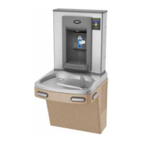
Provides detailed measurements and installation guidelines for rough-in.

Section 2: Rough-In Drawing

Split Level Unit Dimensions

Details dimensions specific to split-level drinking fountain configurations.

Section 3: Installation

A. Drilling the Hole for Water Line Connection

Step-by-step guide for creating the water line entry point on the cooler top.

Section 3: Installation

B. Connecting the Water Line

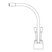
Instructions for connecting the water supply tubing to the bottle filler.

Section 3: Installation

B. Connecting the Water Line (continued)

Details on using tee fittings and routing water lines for the bottle filler.

Section 3: Installation

B. Connecting the Water Line (continued)

Specific procedures for retrofitting the bottle filler to existing cooler units.

Section 3: Installation

B. Connecting the Water Line (continued)

Steps to route and connect the water tubing under the drain.

Section 3: Installation - Final Steps

STEP 5: Attaching Top Cap

Instructions for feeding tubing and reattaching the cooler's top cap.

Section 3: Installation

C. Mounting the Frame to the Wall

Guide for securely mounting the bottle filler frame assembly to the wall.

Section 3: Installation

C. Mounting the Frame to the Wall (continued)

Final steps for attaching the bottle filler, connecting power, and checking for leaks.

Set-Up Guide

Program Settings

How to configure default settings, units, and flow rates for the bottle filler.

Addendum: Pressurizing the Cooling Tank

STEP 1: Unplug Un-insulated Water Line

Initial step to disconnect the main water line from the valve.

Addendum:

Pressurizing Cooling Tank (continued)

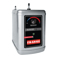
Steps to disconnect and reconnect tubing for pressurizing the cooling tank.

Addendum:

Pressurizing Cooling Tank (continued)

Completing the tubing connections for the cooling tank pressurization process.

Related product manuals