EasyManua.ls Logo

Franklin Electric 2803552115 User Manual

Franklin Electric 2803552115
24 pages
To Next Page IconTo Next Page
Page #1 background imageLoading...
Page #1 background image
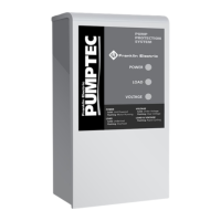
3-wire Submersible Motor
Control Box
0,25 - 3,7 kW
4 - 6
-
Assembly and operation instructions
(Original)
7 - 9
-
Installations- und Bedienungsanleitung
(Übersetzung der Original Installations- und Betriebsanleitung)
10 - 12
-
Istruzioni per il montaggio e I’uso
(Traduzione dell'assemblaggio originale e istruzioni operative)
13 - 15
-
Instructions de montage et de service
(Traduction des instructions d'assemblage et d'utilisation originales)
16 - 18
-
Manual de instrucciones de montaje e servicio
(Traducción de las instrucciones originales de ensamblaje y operación)
19 - 21
-
Manual de Instruções de Montagem e de Serviço
(Tradução das instruções originais de montagem e operação)
22 - 23
-
Appendix-Annexe-Appendice-Anexos-Apêndice
FI
E
P
EN
Franklin Electric Europa GmbH
Rudolf-Diesel-Straße 20
54516 Wittlich / Germany
Phone: +49 (0) 6571 105-0
Fax: +49 (0) 6571 105-520
e-mail: info@franklin-electric.de
www.franklinwater.eu
© Copyright by Franklin Electric 2022
All rights on these instructions – particularly the right to reproduce, distribute and translate – are reserved. No part of the instructions is allowed to be
reproduced in any form (by printing, photocopy, microfilm, or another method) without the prior written authorization by the company Franklin Electric or may
not be processed, reproduced or distributed by use of electronic systems.
We reserve the right to make changes due to technical progress
Declaration of Conformity for 3-wire 1~ Control Boxes:
down load the Declaration of conformity in your Language under: https://franklinwater.eu/more/legal-documents/doc-declaration-of-conformity-products/
D

Questions and Answers:

Franklin Electric 2803552115 Specifications

General IconGeneral
BrandFranklin Electric
Model2803552115
CategoryControl Unit
LanguageEnglish

Summary

EU Declaration of Conformity

UKCA Declaration of Conformity

About This Document

Warnings and Symbols

Warning Notices and Symbols

Explains danger, warning, and note symbols and their meanings for safe operation.

Safety

Intended Use

Specifies the equipment's intended application with Franklin Electric submersible motors.

Liability Exclusion

Outlines conditions under which Franklin Electric is not liable for damages.

Installer Group

Mandates installation by qualified professional staff (electrical technician).

General Safety Instructions

Provides critical safety instructions for operating the control gear.

Storage, Transport, and Disposal

Storage Guidelines

Instructions for proper storage of the control gear before installation.

Transport Conditions

Specifies temperature and humidity requirements during transport.

Unpacking Procedure

Guidance on checking for damage after unpacking and disposing of packaging.

Disposal Information

Information on disposing of electronic components and control gear responsibly.

Technical Specifications and Model Parameters

Power Ratings and Model Numbers

Details power ratings, motor, and control box model numbers, including capacitor specs.

Installation Procedure

Before Installation Checks

Confirms control box current rating matches motor specifications before installation.

Mechanical Installation

Guidance on mounting the control box to a vertical flat surface.

Electrical Installation

Instructions for electrical connection by qualified technicians.

Electrical Wiring Diagram

Details schematic and terminal identification for wiring the control box.

Product Specifications

Electrical Specifications

Details power range, voltage, frequency, phase, and current ratings.

Short Circuit Protection

Lists rated conditional short-circuit current and device current ratings by motor power.

Duty Cycle

Specifies the duty cycle for the control box, noted as 100%.

Mechanical Specifications

Details protection class, environment, pollution degree, dimensions, and mounting.

Storage Temperature

Defines the acceptable temperature range for storing the control box.

Operating Temperature and Humidity

Specifies the operating temperature and humidity limits for the control box.

Transport Temperature and Humidity

Specifies the temperature and humidity limits during transport.

Applicable Standards

Lists the standards the control box complies with, specifically EN 61439-2.

Troubleshooting Guide

Motor/Pump Does Not Switch On

Troubleshooting steps for when the motor or pump fails to start.

Motor/Pump Does Not Switch Off

Troubleshooting steps for when the motor or pump does not stop.

Overload Trips Repeatedly

Addresses issues with repeated overload trips and their remedies.

Appendix: Motor Outlines and Electrical Connection

Wiring Diagram (Figure A)

Illustrates the electrical connections for the control box and motor.

Control Box Dimensions (Figure B)

Provides physical dimensions of the control box for different power ratings.

Appendix: Cable Lengths

Metric Cable Lengths (Figure C)

Details maximum drop cable lengths for various wire sizes and motor ratings.

Related product manuals