Do you have a question about the Frascold R-TSH8 40 120 Y and is the answer not in the manual?
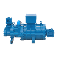
| Oil pump type | Gear pump |
|---|---|
| Frequency | 50 Hz |
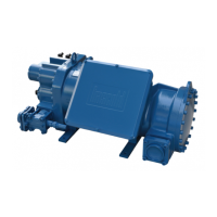
| Type | Semi-hermetic |
| Refrigerant | R404A, R507, R134a |
| Motor voltage | 400V |
| Voltage | 400 V |
Details the standard components supplied with each compressor unit.
Explains the data presented on the compressor's identification name plate.
Procedures for inspecting the compressor upon receipt for damage or missing parts.
Guidelines for safely lifting and moving the compressor using its designated lifting points.
Instructions for securely mounting the compressor to a horizontal base, including torque specifications.
Guidance on brazing refrigerant lines, emphasizing impurity prevention.
Details the essential role and specifications of the oil separator in the lubrication circuit.
Details on setting up the Part Winding Start method for the compressor motor.
Instructions for configuring the compressor for Direct On Line starting.
Steps for adding lubricant to the oil separator, ensuring correct level and type.
Procedure for removing air, moisture, and non-condensables from the refrigeration circuit.
Measuring the supply voltage to ensure it is within acceptable operational limits.
Checking for voltage balance between the power phases for motor protection.
Explains the role of the liquid separator in preventing compressor damage from liquid refrigerant.
Details the function and importance of the temperature actuator for compressor life.
Describes the high-pressure switch for system protection and its correct application.
Details on systems required for cooling lubricant under severe operating conditions.
Instructions for installing air-cooled oil coolers and their temperature control.