The MisMatcher 01 REV.D is an electronic analog video glitcher designed to distort analog video signals using analog circuitry. It works with composite video, specifically the yellow RCA jack from cameras and monitors. The device is engineered to be a powerful yet compact and handy tool for creating video effects.
Function Description:
The MisMatcher 01 contains three different analog circuits: Sync Separator, Sync Mixer, and Enhancer. These circuits can be used individually or interconnected to produce a wide range of video distortions and effects. Feedback and gain controls are available for the Enhancer circuit, allowing for further manipulation of the video signal. The device operates inline, meaning it is connected between the video signal source (e.g., a camera) and its destination (e.g., a monitor).
Important Technical Specifications:
- Size: 100x83 mm
- DC Input: 5 V
- Power Consumption: 170 mA @ 5V
- Video Format: NTSC/480i & PAL/576i
- Voltage Level: 2 Vpk=pk
Usage Features:
Assembly:
The assembly of the MisMatcher 01 REV.D has been simplified compared to previous versions. Most critical components are pre-soldered, requiring users to solder only a handful of jacks and potentiometers, which reduces the chance of human error. The assembly process involves snapping three potentiometers, three gold RCA jacks, and seventeen PJ-341 jacks into place, then securing the PCB and soldering these components. A visual inspection of the solder joints is recommended. The 8-pin male header is assembled later. For the main PCB, the three potentiometers and the piano DIP switch are snapped into place. The power switch and male and female headers are then positioned, and the two PCBs are secured with 8 screws and four standoffs before soldering and visual inspection.
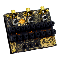
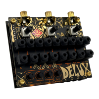
Controls:
The device features a Micro USB Power input, an On/Off Switch, and Oscilloscope probing points for GND, +5V, Composite Sync, Sync Mixer Out, and Enhancer Out. There are three RCA jacks (RCA A, RCA B, RCA C) that serve as access points for video input and output.
Mixer/Attenuators:
The three potentiometers on the user interface can be used for two primary functions:
- Attenuating Video Signal Intensity: By connecting a video source to one of the potentiometer's fixed ends and leaving the other fixed end unplugged, the potentiometer acts as an attenuator. The attenuated signal can be accessed through the wiper jack in the middle. The potentiometer's jacks are automatically connected to ground if no patch cable is inserted.
- Fading Between Two Video Signals: To fade between two video sources, connect one source to each fixed end of a potentiometer. The wiper will then provide a mix of the two signals, allowing for smooth transitions.
Enhancer:
The Enhancer circuit can be used to:
- Boost Saturation and Sharpness: This provides a way to enhance the visual quality of the video signal.
- Distort Video and Create Effects: Using the provided Gain and Feedback 1 and 2 controls, the Enhancer can significantly distort the video. The gain controls the amplification of the signal, while Feedback 1 and 2 take video from different stages of the circuit and feed it back into the Enhancer's input, creating complex and interesting effects. The Enhancer has an input (Enhancer Input) and an output (Enhancer Output), along with controls for Gain amount, Feedback 1 amount, and Feedback 2 amount, as well as enable switches for Feedback 1 and Feedback 2.
Sync Separator and Sync Mixer:
These components are crucial for maintaining or manipulating video stability:
- Sync Separator: Extracts the sync portion of the video signal. A stable sync signal is essential for a stable picture, as distorted sync can lead to horizontal or vertical scrolling on screen.
- Sync Mixer: Takes a video signal connected at the Sync Mixer In and remixes it with the sync provided by the Sync Separator, resulting in a stable image. This can restore sync to a distorted video signal. Alternatively, users can remix a video source with the sync signal from another video source, leading to scrolling images with constructive and destructive interference. The Sync Mixer has an input (Sync Mixer Input) and an output (Sync Mixer Output), along with a Sync Separator Input and two low pass filters (Low pass filter 1 and Low pass filter 2).
Patching Examples:
The manual provides several patching examples to illustrate the device's capabilities:
- Basic Enhancement: Connect a camera to RCA A, a monitor to RCA C. Patch camera A to Enhancer In and monitor A to Enhancer Out. Control enhancement via gain, feedback knobs, and DIP switch.
- Restoring Sync: If the Enhancer causes sync loss, split the camera signal into Sync In and Enhancer In. Patch Enhancer Out into Sync Mixer In, and Sync Mixer Out to the monitor. This restores sync using the original video signal as a reference.
- Sync Mixer as a Glitcher: Split camera A into two potentiometer fixed ends. Patch the first potentiometer's wiper to Sync In, the second to Enhancer In. Patch Enhancer Out to a third potentiometer's fixed end. Patch the third potentiometer's wiper to Sync Mixer In, and Sync Mixer Out to the monitor. The first potentiometer creates a luma keying effect, while the other two act as attenuators. The Sync Mixer's low pass filter can create a ghostly effect.
- Advanced Karl Klomp Style Video Mixer: Connect Camera A to RCA A, Camera B to RCA B, and Monitor A to RCA C. Split Camera A to the first and third potentiometer's fixed ends. Split Camera B to the other fixed ends of the first and third potentiometers. Patch the first potentiometer's wiper to Sync Mixer In, and the third potentiometer's wiper to Sync In. Patch Sync Mixer Out to Monitor C. The first potentiometer acts as a fader between Camera A and B, and the third potentiometer fades between their sync signals, which will be used for the final result.
- Dual Monitor Glitching: Connect Camera A to RCA A, Monitor A to RCA B, and Monitor B to RCA C. Split Camera A into the first potentiometer's fixed end, Sync Mixer In, and Enhancer In. Patch the first potentiometer's wiper to Sync In. Patch Sync Out to Monitor A and Enhancer Out to Monitor B. This allows for separate glitching of one camera with the Sync Mixer and Enhancer, sending each to a respective monitor.
Maintenance Features:
- Cleaning: Clean the apparatus only with a dry cloth.
- Power Supply: Use a USB charger and Micro USB cable for power. If horizontal lines appear on the screen, replace the USB charger, as it may be noisy.
- Servicing: Refer all servicing to qualified service personnel. Servicing is required if the apparatus is damaged (e.g., damaged power cord/plug, spilled liquid, fallen objects, exposure to rain/moisture, abnormal operation, or if it has been dropped).
- Safety Precautions:
- Read and keep all instructions and heed all warnings.
- Do not use near water or heat sources.
- Protect the power cord from being walked on or pinched.
- Use manufacturer-specified attachments/accessories and ensure external equipment is installed according to safety specifications.
- Unplug during lightning storms or prolonged periods of disuse.
- Prevent objects from falling into and liquids from spilling into the enclosure. Do not expose to rain or moisture.
Warranty:
Fully assembled versions of the MisMatcher 01 are covered by a one-year warranty from the date of purchase. This warranty covers manufacturing defects, assembly errors, or faulty components. It does not cover damage or malfunction caused by incorrect use, such as reversed power cables, excessive voltage, or exposure to extreme temperatures or moisture. The customer is responsible for the cost of returning a product for repair or replacement. DIY kits and bare printed circuit boards are not covered under any warranty and do not include assembly troubleshooting or customer support.