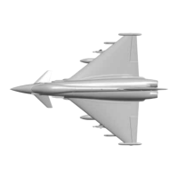
This document describes the Freewing Eurofighter Typhoon, a model aircraft designed for experienced users. It provides detailed assembly instructions, technical specifications, usage precautions, and maintenance guidelines.
Function Description
The Freewing Eurofighter Typhoon is a remote-controlled model aircraft. It features a PNP (Plug-N-Play) configuration, meaning most electronic components are pre-installed, requiring only final assembly and setup by the user. The model is designed for flight and includes functionalities such as aileron, canard, rudder, and a unique reverse thrust feature. The control board is pre-set for delta wing and canard wing mixing, simplifying remote control setup to a standard fixed-wing mode.
Important Technical Specifications
Standard Version:
- Wingspan: 1030mm (40.5 in)
- Length: 1450mm (57.1 in)
- Wingload: 129 g/dm²
- Wing Area: 31 dm²
- Empty Weight: 3230g (w/o Battery)
- Motor: 3668-1960KV I/R Motor
- Servos:
- 9g Hybrid digital servo ×4
- 9g MG digital servo ×2
- 17g MG digital servo ×3
- ESC: 120A Brushless ESC (with Thrust Reverse Function)
- Ducted Fan: 90mm 12-blade fan
- Material: EPO
- Control Surfaces: Aileron (Yes), Canard (Yes), Rudder (Yes)
- Landing Gear: Electric Landing Gear (Nose gear cabin door, Rear gear cabin door)
- Scale Pilot Figure: Included
- Recommended Li-Po Battery: 6S 5000-6000mAh (1pcs), Discharge rate of C ≥ 35C
- Battery Cabin Size: L=180mm, W=70mm, H=55mm
- Battery Weight: 760g
Motor Specification (3668-1960):
- Item No.: MI036681
- EDF Fans: 90mm 12-Blade
- Use Voltage (V): 22.2
- Current (A): 110
- Max Power (W): 2442
- Thrust (g): 4300
- Efficiency (g/w): 1.76
- Motor (KV): 3668-1960
- Use ESC (A): 120
- Weight (g): 400
Servo Specifications (Pre-installed):
- Nose gear steering servo: 9g Digital-Hybrid, Positive, 200mm cable length
- Landing gear door: 9g Digital-Hybrid, Positive, 200mm cable length
- Rear cabin door left: 9g Digital-Hybrid, Positive, 500mm cable length
- Rear cabin door right: 9g Digital-Hybrid, Reverse, 500mm cable length
- Aileron (L): 17g Digital-MG, Positive, 300mm cable length
- Aileron (R): 17g Digital-MG, Positive, 300mm cable length
- Canard (L): 9g Digital-MG, Positive, 400mm cable length
- Canard (R): 9g Digital-MG, Positive, 400mm cable length
- Rudder: 17g Digital-MG, Positive, 100mm cable length
Usage Features
Assembly:
- Fuselage: Tail foam part and tail nozzle are installed using glue.
- Canard: Installed by turning the fuselage belly up, inserting the canard into the rotating shaft, aligning screw holes, and fixing with KM3X6mm screws (2PCS).
- Main Wing: LED light plugs of wingtip and main wing are connected (observing positive and negative poles). Left/right wingtip cowlings are installed and fixed with KA3X10mm screws (4PCS). The main wing is attached to the fuselage by opening the rear cabin door, inserting the ribbon wire to the main wing control board, and fixing with M4X16mm screws (6PCS).
- Vertical Stabilizer: Rudder servo extension cable and fuselage extension cable are connected, then the vertical stabilizer is installed with KA3X10mm screws (4PCS).
- Nose Cone: Attaches via magnetic adsorption.
- Missiles and Bombs: Installed on designated pylons.
- Small Plastic Parts: Includes missile, landing hook, and antennas, which are installed in specific locations.
Battery Installation and Connection:
- The battery is installed in the cockpit.
- Before connecting the battery and receiver, ensure the transmitter is on and the throttle stick is in the lowest position.
- Bind the receiver to the transmitter according to the transmitter's manual.
Pushrod Instructions:
- Detailed diagrams and lengths are provided for nose gear steering (55mm), nose cabin door (41.5mm), rear follow-up cabin door (15mm), rear cabin door (15mm), aileron (90mm), rudder (90mm), and canard (40mm) pushrods, along with their respective mounting hole positions. All pushrods have a diameter of Ø1.2mm or Ø1.5mm.
- Y-type clevises are equipped with transparent silicone rings for secondary reinforcement to prevent accidental loosening.
Center of Gravity (CG):
- Correct CG is crucial for stability and control. The recommended CG is 215mm from the leading edge of the main wing, marked on the bottom of the wing.
- Adjust CG by moving the battery forward or backward. Counterweights are generally not needed with the recommended battery size.
Canard Wing Installation Diagram:
- The canard wing installation position is indicated by a scale line on the fuselage; align the leading edge of the canard with this line.
Setting and Adjustment Instructions:
- The Eurofighter control board has pre-set delta wing and canard wing mixing. Users only need to set the remote control to normal fixed-wing mode.
- Canard Control Direction: If the elevator control direction of Canard 1 and Canard 2 is incorrect, exchange the two canard plugs on the control board.
- Aileron Control Direction: If the elevator control direction of Aileron 1 and Aileron 2 is incorrect, exchange the two six-pin-plugs on the control board.
- Rear Cabin Door Mode Switch:
- Switch On (Dual Stage Mode): Door Open → Gear Down → Door Close, then Door Open → Gear Up → Door Close.
- Switch Off (Single Stage Mode): Door Open → Gear Down, then Door Open → Gear Up.
Control Direction Test:
- After assembly, with a fully charged battery connected to the ESC, use the radio to test and ensure all control surfaces (aileron, canard, rudder) operate correctly according to stick inputs (left, right, down, up).
Dual Rates and EXP Setting Suggestion:
- Recommended parameters for Aileron/Elevator Rate and Exponential (%) are provided based on testing experience.
- Low Rate:
- Main Wing Aileron: H1/H2 16mm/16mm, D/R Rate: 40%
- Main Wing Elevator: H1/H2 35mm/35mm, D/R Rate: 80%
- Canard Aileron: H1/H2 10mm/10mm, D/R Rate: 40%
- Canard Elevator: H1/H2 20mm/20mm, D/R Rate: 80%
- Rudder: H1/H2 27mm/27mm, D/R Rate: 80%
- High Rate:
- Main Wing Aileron: H1/H2 24mm/24mm, D/R Rate: 60%
- Main Wing Elevator: H1/H2 43mm/43mm, D/R Rate: 100%
- Canard Aileron: H1/H2 15mm/15mm, D/R Rate: 60%
- Canard Elevator: H1/H2 26mm/26mm, D/R Rate: 100%
- Rudder: H1/H2 32mm/32mm, D/R Rate: 100%
- EXP Setting (Futaba/Spektrum):
- Aileron EXP: Futaba EXP A -30, EXP B -30; Spektrum EXPO 30% 30%
- Elevator EXP: Futaba EXP A -30, EXP B -30; Spektrum EXPO 30% 30%
- Rudder EXP: Futaba EXP A -30, EXP B -30; Spektrum EXPO 30% 30%
- High Rate is recommended for the first flight; switch to Low Rate for lower sensitivity. Adjust rates and expo to personal preference on subsequent flights.
Maintenance Features
General Precautions:
- This is not a toy. Operators should have experience; beginners require professional guidance.
- Read instructions carefully and operate strictly as instructed to avoid damage or loss.
- Freewing is not responsible for losses due to wrong operation.
- Model plane players must be 14 years or older.
- The plane is made of EPO material with surface spray paint; do not use chemical cleaners to avoid damage.
- Avoid flying in public places, high-voltage areas, near highways, airports, or any restricted areas.
- Do not fly in bad weather (thunderstorms, snow).
- Battery Safety: Do not place batteries anywhere. Store them ensuring no inflammable or explosive materials are within a 2M radius.
- Damaged or scrap batteries must be properly recycled; do not discard to prevent spontaneous combustion or fire.
- Properly handle waste after flying; do not abandon or burn it.
- Always ensure the throttle is in the low position and the transmitter switch is on before connecting the LiPo battery to the aircraft.
- Do not attempt to hand-launch or catch the plane during flight or slow landing. Wait for it to stop completely before handling.
ESC Calibration:
- Before the first flight and after replacing the remote control, the ESC needs to be calibrated to the throttle to ensure maximum thrust from the EDF power system.
Reverse Thrust Function:
- To use the reverse thrust function, the reverse thrust signal cable must be inserted into an idle switch channel of the receiver (signal range consistent with throttle travel).
- This channel controls forward and reverse motor rotation.
- Channel travel 0-50% is for default direction; 50-100% triggers reverse rotation.
- When reverse is triggered, the motor stops, then reverses and accelerates according to throttle stick output.
- When powering on for the first time, the rocker position of this channel should be within 0-50% of the channel travel (preferably 0) to avoid a throttle signal loss alarm.
Servo Direction:
- Servo positive or reverse rotation is defined by input signal change from 1000µs to 2000µs. Clockwise rotation is positive, counter-clockwise is reverse.
- A list of pre-installed servo types, their regulation (positive/reverse), and cable lengths is provided for reference if purchasing other brand servos.