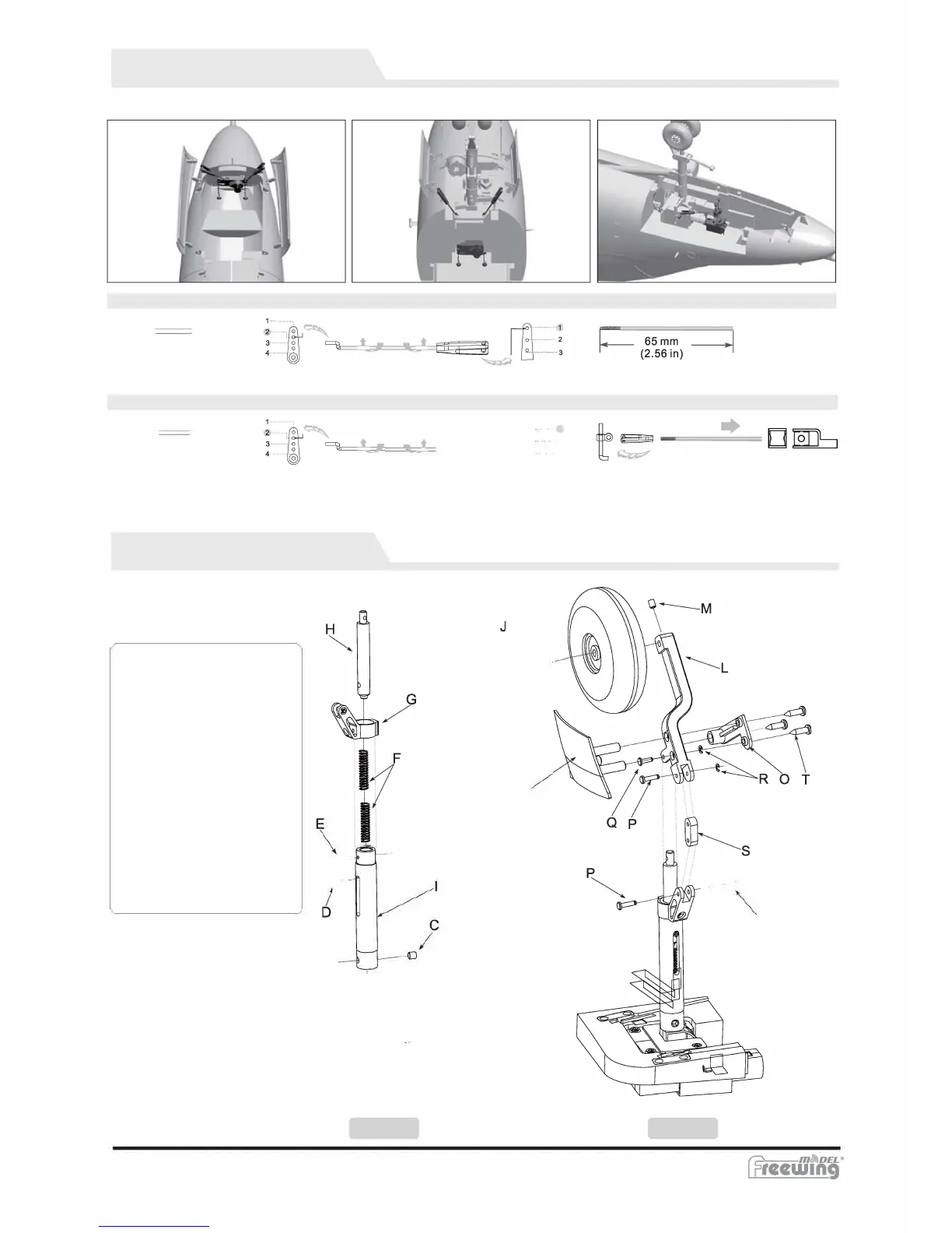
Nose Gear Door Assembly
Refer to the following photos to assemble/disassemble gear doors.
Nose gear door pushrod size (front) Recommended servo pushrod installation hole
(1.29 in)
Nose gear door pushrod size(rear) Recommended servo push rod installation hole
(2.68 in)
1
a
Main Landing Gear Assembly
Assemble/disassemble rear landing gear
by referring to the following diagrams.
P
ar
t
s
:
A. Electric retract
B. Grub Screw (M3x5mm)
C. Grub screw (M4x4mm)
D. Screw (m3x5.2mm)
E. Screw (PA2x4mm)
F. Spring
G. Upper connecting arm
H. Shock absorbing arm
I. Landing gear strut
J. Rear wheel axle
K. Wheel (060/16mm)
L. Lower gear strut
M. Grub screw (m3x3mm)
N. Main gear door
O. Door connector
P. Pin
Q. Pin
R. E clip
S. Connecting arm
T. Screw (PA2.6x10mm)
T-45 Goshawk
/
A�
Step 1
-8-
K
\
N
EN
Nose steering push rod size
Recommended servo pushrod installation hole
R
Step2