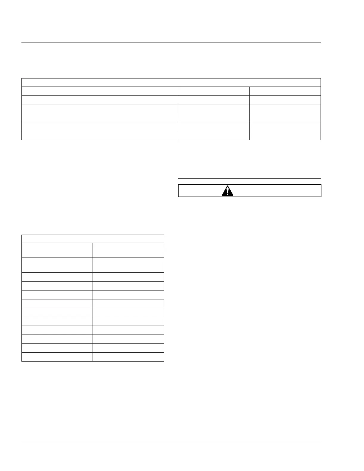
Suspension Torque Specifications (lubricated threads)
Description Size Torque: lbf·ft (N·m)
Equalizing Beam Center Bushing Locknut 3/4–16 150 to 200 (203 to 271)
Equalizing Beam Front Bushing Locknut
1-1/8–12
600 to 700 (814 to 949)
1-1/4–12
Control Rod Ball Stud Locknut 1-1/8–12 550 to 650 (746 to 881)
Control and Torque Rod Mounting Locknuts 5/8–18 110 to 150 (149 to 203)
Table 1, Suspension Torque Specifications (lubricated threads)
NOTE: Height control valves control all front and
rear suspension air springs. Check for air leaks
by applying a soapy solution. Then, check for
bubbles at all air connections and fittings.
5. Check the ride height of the air suspension by
measuring the distance from the center of the
lower shock bolt to the bottom of the frame rail.
See
Fig. 1. See Table 2 for height control valve
adjustment measurements. If ride height is incor-
rect, adjust the air suspension.
Height Control Valve Adjustment Measurements
Suspension
Measurement
Inches ±1/4 (mm ±6)
AS120 (front)
10 (254) or
10-1/2 (267)
*
AS140 (front) 11 (279)
IFS114 (front) 17-1/2 (445)
IFS ZF (front) 15-3/4 (400)
ADL-RS17/19/21 10-1/4 (260)
AD200-RS17/19 9-3/4 (248)
AD200-RS15 9-3/8 (238)
ADTB280 (rear) 17-1/4 (438)
Airliner 15k (rear) 8-3/4 (222)
AD123 (rear) 18 (457)
ADL123 (rear) 11 (279)
*
Some vehicles have a different shock location. When this is the case, the
vehicle will have a 55 degree wheel cut. Ride height for these vehicles
should be set at 10-1/2 inches (267 mm).
Table 2, Height Control Valve Adjustment
Measurements
32–03 Neway Suspension
Inspection
WARNING
Inspect the components and check their operation
as described below. Failure to perform these in-
spections and checks could result in separation of
worn suspension components and loss of vehicle
control, possibly causing personal injury or death,
or property damage.
1. Chock the front or the rear tires. Working at the
front of the vehicle or at the rear of the vehicle,
raise the vehicle so that the tires just clear the
ground and the suspension is fully extended.
Place safety stands under the vehicle frame.
2. Squeeze all air springs to check for complete
deflation. It may take ten minutes for the pres-
sure to bleed down from the air spring. See
Fig. 2. If any air springs remain partially or fully
inflated, see Group 32 of the Recreational Ve-
hicle Chassis Workshop Manual, or take the ve-
hicle to an authorized Freightliner dealer. Inspect
the air springs for cracks, tears, or other dam-
age.
3. Inspect each air spring for wear at the pedestal
connection. Inspect for leaks at the upper and
lower pedestal connections using a soapy solu-
tion. Replace any worn air springs; for instruc-
tions, see Group 32 of the Recreational Vehicle
Chassis Workshop Manual, or take the vehicle to
an authorized Freightliner dealer.
4. Inspect the bolts and nuts at the pivot connec-
tions, the transverse beam connections, and the
axle connections to ensure they are tightened to
the correct torque specification.
Suspension32
Recreational Vehicle Chassis Maintenance Manual, June 201532/2
 Loading...