EasyManua.ls Logo

FRIDEN STW - Page 157

Default Icon
161 pages
Print Icon
To Next Page IconTo Next Page
To Previous Page IconTo Previous Page
Loading...
“paged
FRIDEN
CALCULATING
MACHINE
Co.,
INC.
nest
MODEL
STW
AUTOMATIC
TRANSFER
MECHANISM
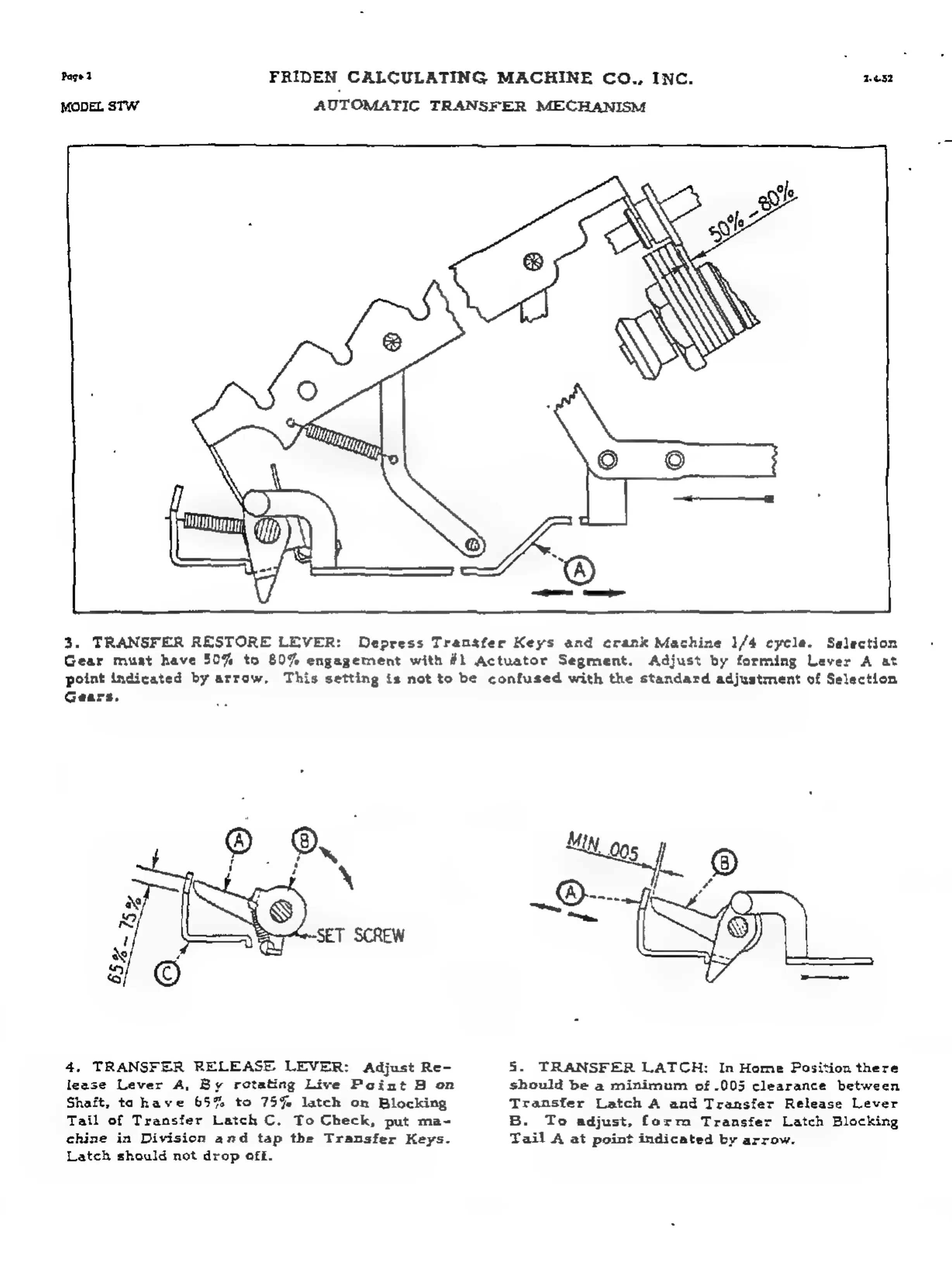
3.
TRANSFER
RESTORE
LEVER:
Depress
Transfer
Keys
and
crank
Machine
1/4
cycle.
Selection
Gear
muat
have
50%
to
80%
engagement
with
#1
Actuator
Segment.
Adjust
by
forming
Lever
A
at
point
indicated
by
arrow,
This
setting
is
not
to
be
confused
with
the
standard
adjustment
of
Selection
Gears.
4,
TRANSFER
RELEASE.
LEVER:
Adjust
Re-
5.
TRANSFER
LATCH:
In
Home
Position
there
lease
Lever
A,
By
rotating
Live
Point
8
on
should
be
a
minimum
of
.005
clearance
between
Shaft,
tahave
65%
to
75%
latch
on
Blocking
Transfer
Latch
A
and
Transfer
Release
Lever
Tail
of
Transfer
Latch
C.
To
Check,
put
ma-
B.
To
adjust,
form
Transfer
Latch
Blocking
chine
in
Division
and
tap
the
Transfer
Keys.
Tail
A
at
point
indicated
by
arrow.
Latch
should
not
drop
off.