S
Steven ClarkAug 18, 2025
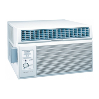
Why is my Friedrich Air Conditioner not cooling properly?
- AAndrew RamirezAug 18, 2025
If your Friedrich air conditioner isn't cooling well, several factors could be the cause: * Make sure the thermostat is set to the coldest position and test it. Replace if necessary. * A dirty air filter can restrict airflow. Clean it as recommended in the Owner's Manual. * Dirty or plugged condenser or evaporator coils can also reduce cooling efficiency. Clean the coils. * Poor air circulation in the room can impact cooling. Adjust the air louvers, check the application, inspect for a dirty filter or evaporator coil, and check the fan motor. Correct as needed. * Low refrigerant levels due to a leak can cause poor cooling. Check for leaks and repair them. * If the compressor isn't pumping properly, it may need to be replaced.