EasyManua.ls Logo

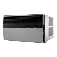
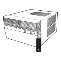
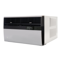
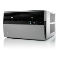
Friedrich KUHL R-410A User Manual

Friedrich KUHL R-410A
87 pages
To Next Page IconTo Next Page
Page #1 background imageLoading...
Page #1 background image
Service Manual
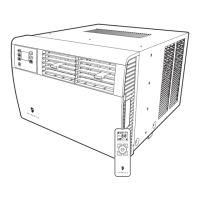
Standard Chassis R-410A Models
Room Air Conditioners
115-Volt:
208-230-Volt:
Cool Only
SS08M10, SS10M10, SS12M10, SS14M10
SS12M30, SS15M30, SM18M30, SM21M30
SM24M30, SL28M30, SL36M30
Cool with Electric Heat
208-230-Volt: ES12M33, ES15M33, EM18M34, EM24M35, EL36M35
Heat Pump with Electric Heat
208-230-Volt: YS12M33, YM18M34, YL24M35
Heat Pump
115-Volt: YS10M10
SYSTEM FAN MODE
SCHEDULE FAN SPEED
AUTO
AUTO
AUTO
CONTINUOUS
°F °C
Kuhl-ServMan (5-10)

Table of Contents

Questions and Answers:

Friedrich KUHL R-410A Specifications

General IconGeneral
BrandFriedrich
ModelKUHL R-410A
CategoryAir Conditioner
LanguageEnglish

Summary

Important Safety Information

Personal Injury and Death Hazards

Covers electrical, refrigeration, and mechanical hazards.

Property Damage Hazards

Fire and Water Damage Risks

Risks of fire or water damage from improper operation or installation.

Introduction

Unit Identification and Model Location

Where to find model and serial numbers for unit identification.

Unit Identification

Performance Data and Specifications

Installation Information

Sleeve Dimensions and Circuit Rating

Details on sleeve sizes and electrical circuit requirements.

Electrical Data and Safety

Pre-Operation Warnings

Wiring, Cords, and Receptacle Checks

Ensures correct wiring, dedicated circuits, and proper receptacles.

Power Cord Testing Procedure

Procedure for testing the LCDI power cord.

Control Panel Operation

Display and Basic Controls

Explains the LCD display and basic control buttons.

Fan Speed and Scheduling Settings

How to select fan speeds and use the schedule function.

Temperature Adjustment

Using UP/DOWN buttons for temperature settings.

System Alerts and Special Functions

Alerts: Filter, Maintenance, Wait, Freeze, Battery

Identifies and explains system alerts for maintenance and operation.

Special Functions: Panel Lock & Filter Reset

Functions for panel locking and resetting filter reminders.

User Menu Navigation and Time Setting

Accessing and navigating the user menu and setting time.

Control Panel User Menu Options

Clock, Emergency Heat, and Alerts Settings

Settings for clock format, emergency heat, and alert sounds.

Dead Band and Temperature Units

Adjusting auto changeover dead band and temperature units.

Advanced Control Functions

Freeze Protection and Temperature Offset

Features for preventing freezing and adjusting temperature readings.

Auto Sampling, Firmware, and Error Code Summary

Auto temp sampling, firmware display, and error code summary.

Remote Control Operation Basics

Getting Started and Basic Operation

Installing batteries and operating the remote control.

Key Button Functions

Explains key buttons for mode, fan, and scheduling.

Remote Effectiveness and Range

Information on the remote's operating range and signal strength.

Electronic Control System Maintenance

Introduction and Display Indicators

Overview of maintenance alerts and display indicators.

Testing the Control Panel Display

Procedure to verify the functionality of the control panel display.

Maintenance Section Navigation

Entering Maintenance Menus and Sub-Menus

How to access and navigate maintenance sub-menus (M1-M6).

Maintenance Menu Functions

Temperature Limit Adjustments

Adjusting temperature limits.

System Test Mode Access

Accessing and using the system test mode.

Maintenance Menu: Configuration and Errors

Unit Configuration and Error Code Management

Factory settings, viewing/clearing error codes, and history.

Unit Operation Modes

Front Panel Operation and System Modes

Operating the unit via the front panel and system mode sequences.

Cool/Heat Set Point Configuration

Set Point Mapping and List

How set points relate to internal controls and available set points.

Electronic Control Sequence of Operation

Compressor and Reversing Valve Control

States of compressor and reversing valve in different modes.

Cooling Mode Operation Details

Detailed steps of the cooling cycle, including delays.

Heating Mode Control Operation

Heat Pump Only Heating Control

Operation sequence for heat pump heating cycles.

Heat Pump with Electric Heat Operation

Electric Heat Activation Conditions

How temperature and delta affect switching to electric heat.

Emergency Heat and Auto Modes

Emergency heat function and automatic cool/heat changeover.

Compressor and Fan Operation Logic

Compressor Lock Out and Wait Icon

Compressor lockout timing and wait icon indicators.

Fan Delays and System Modes

Fan delays in cooling/heating and Fan Only mode rules.

Fan Operation Details

Fan Speeds, Icons, and Mapping

Fan speed selection, icon display, and relay mapping.

Unit Operation with Wall-Stat

Wall-Stat Mode Display and Thermostat Requirements

Front panel behavior and thermostat terminal needs.

Removing Unit Components

Front Cover and Chassis Removal

Procedures and warnings for removing front cover and chassis.

Component Replacement Procedures

Indoor Coil Thermistor & Control Board Replacement

Steps for replacing the indoor coil thermistor and control board.

Low Voltage Interface and Thermostat Connection

Adding a Remote Wall Thermostat

Selecting and connecting a remote wall thermostat.

Thermostat Wiring and Terminal Requirements

Wiring diagrams and terminal requirements for thermostats.

Thermostat Location and Airflow Adjustment

Remote Thermostat Location & Airflow Controls

Proper thermostat placement and adjusting airflow direction/fresh air.

Desk Control and Auxiliary Fan Wiring

Connecting desk controls and auxiliary fan relays.

Components Testing: Motors and Capacitors

Fan Motor Testing

Procedures for testing fan motors.

Capacitor Testing and Connections

Procedures for testing and connecting capacitors.

Components Testing: Heating and Drain

Heating Element Testing

Procedures for testing heating elements.

Drain Pan Valve Operation

Explanation of the drain pan valve's function.

Refrigeration Sequence of Operation

R-410A System Repair Considerations

R-410A Sealed System Repair Procedures

Required Equipment and Capabilities

Lists necessary tools and equipment for refrigerant system repairs.

Refrigerant Charging Principles

Importance of correct refrigerant charge for unit performance.

Refrigerant Charging Method

Refrigerant System Diagnosis

Undercharged and Overcharged Systems

Symptoms and checks for refrigerant under/overcharging.

Restricted Refrigerant Systems

Hermetic Components Check

Metering Device and Check Valve Operation

Checks for capillary tube restrictions and check valve function.

Reversing Valve Description and Operation

Testing and Checking the Reversing Valve

Solenoid Coil and Valve Operation Checks

Procedures to test the solenoid coil and overall valve operation.

Reversing Valve Troubleshooting Tests

Touch Test and Replacement Procedure

Performing touch tests and steps for valve replacement.

Compressor Checks and Overload Testing

Locked Rotor, Amperage Tests, and Overloads

Procedures for testing compressor voltage, amperage, and overloads.

Compressor Electrical and Efficiency Tests

Resistance, Ground, and Efficiency Tests

Tests for motor resistance, grounding, and compressor efficiency.

Compressor Replacement Procedure

Motor Compressor Burnout Procedure

Routine Maintenance Overview

Cleaning Coils, Blower, and Electronics

Maintenance tasks for coils, blower, fan, housing, and electronic parts.

Routine Maintenance Continued

Sleeve, Drain, Front Cover, and Clearances

Maintenance for sleeve, drain, front cover, and unit clearances.

Routine Maintenance: Filter Servicing

Standard Filter Cleaning and Installation

Step-by-step guide for filter maintenance.

Routine Maintenance: Start-up and Operational Notes

Start-up Checklist and Operational Notes

Checklist for post-maintenance startup and notes on operation.

Control Panel Battery Replacement

Procedure for replacing the control panel battery.

Service and Assistance Information

Obtaining Service and Available Accessories

How to get service and a list of available accessories.

Performance Test Data Sheet

Error Codes and Alarm Status

General Troubleshooting Tips

Troubleshooting Tips (Continued)

Troubleshooting: Cooling Only Models

Troubleshooting: Cooling Only Models (Continued)

Troubleshooting: Cooling Only Models (Continued)

Troubleshooting: Cooling Only Models (Continued)

Troubleshooting: Heat/Cool Models

Troubleshooting: Heat Pump Models

Troubleshooting: Heat Pump Models (Continued)

Reversing Valve Troubleshooting Chart

Electronic Control Board Components

Remote Wall Thermostat Wiring Diagrams

Kühl Cool Only Models Wiring Diagram

Kühl Cool Only Models Wiring Diagram

Kühl+ Cool with Electric Heat Wiring Diagram

Kühl+ Cool with Electric Heat Wiring Diagram

Kühl+ Heat Pump Only Model Wiring Diagram

Kühl+ Heat Pump with Electric Heat Wiring Diagram

Kühl+ Heat Pump with Electric Heat Wiring Diagram

Thermistor Resistance Values

Remote Control Configuration Instructions

Checking Remote Control OPT Code

Kühl User Interface Service Kit

Cooling Load Estimate Form Instructions

Cooling Load Estimate Form

Heat Load Form Instructions

Heating Load Form

Limited Warranty Information

Technical Support Contact Information

Related product manuals