86 PB
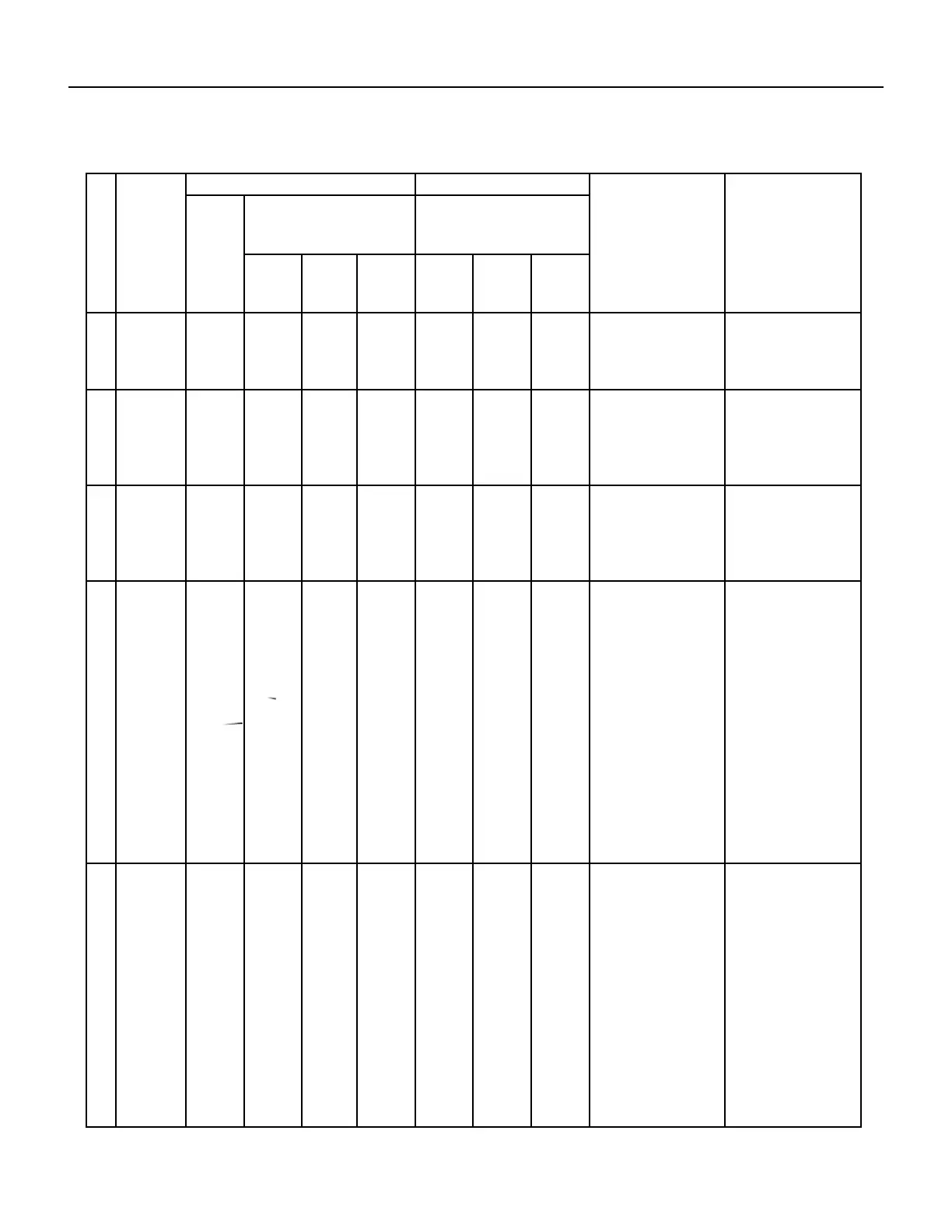
No. Malfunction
Name
Display Method of Indoor Unit Display Method of Outdoor Unit A/C status Possible Causes
Dual-8
Code
Display
Indicator Display (During blinking,
ON 0.5s and OFF 0.5s)
Indicator has 3 kinds of display
status and during blinking, ON
0.5s and OFF 0.5s
Power
Indicator
Cool
Indica-
tor
Heating
Indicator
Yellow
Indicator
Red Indi-
cator
Green
Indicator
18 decrease
frequency
due to over-
current
F8 OFF 3s
and blink
8 times
OFF 1s
and blink
once
All loads operate normally,
while
operation frequency for
compressor is decreased
The input supply voltage is
too low; System pressure is
too high and overload
19 decrease
frequency
due to
high air
discharge
F9 OFF 3s
and blink
9 times
OFF 1s
and blink
twice
All loads operate normally,
while
operation frequency for
compressor is decreased
Overload or temperature
is too high; refrigerant is
insufcent Malfunction of
electric expansion valve
(EKV)
20 limit/
decrease
frequency
due to anti-
freezing
FH OFF 3s
and blink
2 times
OFF 3s
and blink
2 times
OFF 1s
and blink
4 times
All loads operate normally,
while operation frequency
for compressor is de-
creased
Poor air-return in indoor
unit or fan speed is too low
21 voltage for
DC bus bar
is too high
high
PH OFF 3s
and blink
11 times
OFF 1s
and blink
13 times
During cooling and drying
operation, compressor will
stop while indoor fan will
operate; During heating
operation, the complete unit
will stop operation.
1.Measure the voltage of
position L and N on wiring
board (XT), if the voltage is
higher than 265VAC, turn
on the unit after the supply
voltage is increased to the
normal range.
2.If the AC input is normal,
measure the voltage of
electrolytic capacitor C on
control panel (AP1), if its
normal, theres malfunc-
tion for the circuit, please
replace the control panel
(AP1)
22 voltage of
DC bus- bar
is too low
PL OFF 3s
and blink
21 times
OFF 1s
and blink
12 times
During cooling and drying
operation, compressor will
stop while indoor fan will
operate; During heating
operation, the complete unit
will stop
1.Measure the voltage of
position L and N on wiring
board (XT), if the voltage is
higher than 150VAC, turn
on the unit after the supply
voltage is increased to the
normal range.
2.If the AC input is normal,
measure the voltage of
electrolytic capacitor C on
control panel (AP1), if its
normal, there is a malfunc-
tion for the circuit, replace
the control panel (AP1)
TROUBLESHOOTING
Diagnostic Codes
 Loading...