EasyManua.ls Logo

Friedrich MW18Y3F User Manual

Friedrich MW18Y3F
18 pages
To Next Page IconTo Next Page
Page #1 background imageLoading...
Page #1 background image
SPLIT TYPE
ROOM AIR CONDITIONER
WALL MOUNTED
type
ERROR CONTENTS ..................
Models
Indoor unit Outdoor unit
MW18Y3F MR18Y3F
CONTENTS
SPECIFICATIONS ..................... 1
OUTLINE AND DIMENSIONS ........... 2
STANDARD ACCESSORIES ........... 16
REFRIGERANT SYSTEM DIAGRAM ..... 3
CIRCUIT DIAGRAM ................... 4
INDOOR PCB CIRCUIT DIAGRAM 5
OUTDOOR PCB CIRCUIT DIAGRAM 8
10
....
......
DISASSEMBLY ILLUSTRATION ........ 11
PARTS LIST ........................ 14
Question and Answer IconNeed help?

Do you have a question about the Friedrich MW18Y3F and is the answer not in the manual?

Friedrich MW18Y3F Specifications

General IconGeneral
Cooling Capacity18, 000 BTU
Voltage208/230 V
Fan Speeds3
Refrigerant TypeR-410A
Amperage8.0 A

Summary

Specifications

Cooling and Heating Capacity

Rated cooling and heating output of the air conditioner.

Electrical Data

Key electrical operating parameters including voltage, frequency, and current.

Refrigerant Specifications

Details the refrigerant type and full charge quantity.

Dimensions

Indoor Unit Dimensions

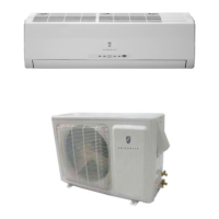
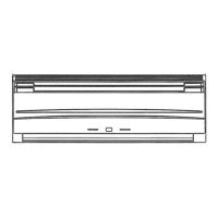
Detailed physical measurements of the indoor unit.

Outdoor Unit Dimensions

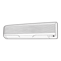
Detailed physical measurements of the outdoor unit.

Refrigerant System Diagram

Refrigerant Pipe Diameter

Specifications for the refrigerant pipe sizes for liquid and gas.

Circuit Diagrams

Indoor Unit Circuit Diagram

Detailed electrical schematic for the indoor unit.

Outdoor Unit Circuit Diagram

Detailed electrical schematic for the outdoor unit.

PCB Circuit Diagrams

Indoor PCB Circuit Diagram

Detailed electrical schematic for the indoor unit's PCB.

Controller PCB Assembly

Detailed electrical schematic for the controller PCB assembly.

Indicator PCB Assembly

Detailed electrical schematic for the indicator PCB assembly.

Outdoor PCB Circuit Diagram

Inverter Assembly and Wiring

Schematic of the outdoor unit's inverter and controller connections.

Error Contents

Serial Signal and Thermistor Errors

Covers serial signal and thermistor related error codes.

Control and Fan Motor Errors

Details errors for unit control and fan motor operation.

Refrigerant and Optional Function Errors

Covers refrigerant cycle and optional function errors.

Disassembly Illustrations

Indoor Unit Exploded View

Exploded view showing indoor unit parts for disassembly.

Outdoor Unit Exploded View

Exploded view showing outdoor unit parts for disassembly.

Parts List

Indoor Unit Parts

Comprehensive list of indoor unit components and their part numbers.

Outdoor Unit Parts

Comprehensive list of outdoor unit components and their part numbers.

Standard Accessories

Wall Hook Bracket

Accessory for mounting the unit.

Remote Control Unit

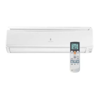
Included remote control for unit operation.

Air Cleaning Filter

Filter component for air purification.

Related product manuals