TTJ-0198 (10/97) (Page 22 of 64)
DEFROST BULB LOCATION
(Heat Pump Models Only)
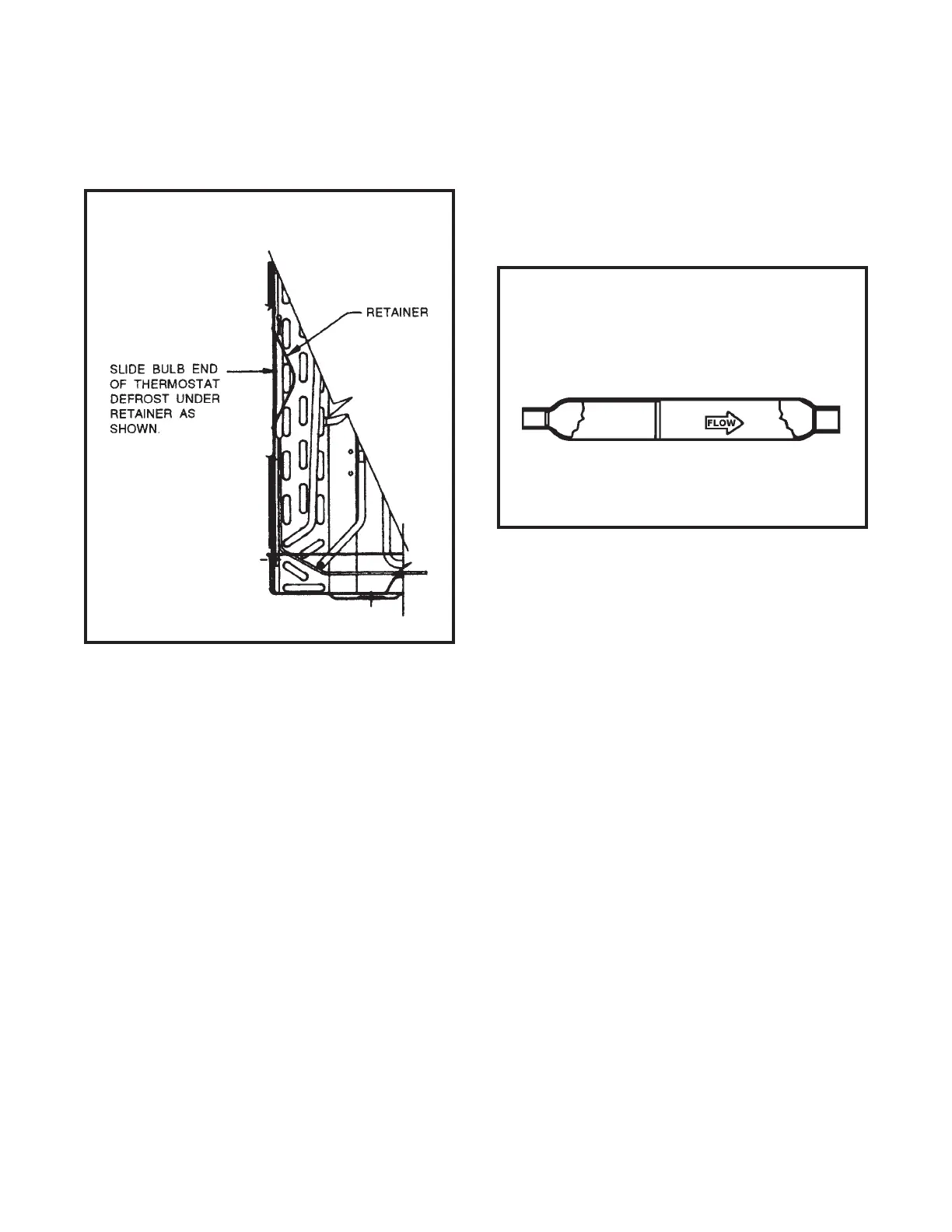
The defrost control bulb must be mounted securely and
in the correct location to operate properly (see Figure
14.)
Figure 14: DEFROST THERMOSTAT BULB
LOCATION (All Heat Pump Models)
CHECK VALVE (Figure 15)
(Heat Pump Models Only)
A one-way check valve is installed in the capillary tube
circuit to allow the flow of refrigerant through both tubes
to the evaporator during the cooling mode.
In the heating mode, one capillary is closed by the check
valve to allow flow through one capillary only to the con-
denser.
Figure 15: ONE-WAY CHECK VALVE
(Heat Pump Models)
NOTE: The slide (check) inside the valve is made of
teflon. Should it become necessary to replace
the check valve, place a wet cloth around the
valve to prevent overheating during the brazing
operation. The flow arrow on the valve must point
toward the evaporator.
VALVE, DRAIN PAN (see Figure 16)
During the cooling mode of operation, condensate which
collects in the drain pan is picked up by the condenser
fan blade and sprayed onto the condenser coil. This
assists in cooling the refrigerant plus evaporating the
water.
During the heating mode of operation, it is necessary
that water be removed to prevent it from freezing during
cold outside temperatures. This could cause the con-
denser fan blade to freeze in the accumulated water
and prevent it from turning.
To provide a means of draining this water, a bellows
type drain valve is installed over a drain opening in the
base pan.
SOLENOID COIL
(Heat Pump Models Only)
The solenoid coil is an electromagnetic type coil mounted
on the reversing valve and is energized during the op-
eration of the compressor in the heating cycle.
Should the reversing valve fail to shift during the heat-
ing cycle, test the solenoid coil. Also, refer to Touch Test
Chart on page 26.
TO TEST:
1. Disconnect power to unit.
2. Disconnect coil leads.
3. Attach probes of ana ohmmeter to each coil lead
and check for continuity.
NOTE: Do not start unit with solenoid coil removed from
valve, or do not remove coil after unit is in op-
eration. This will cause the coil to burn out.
 Loading...