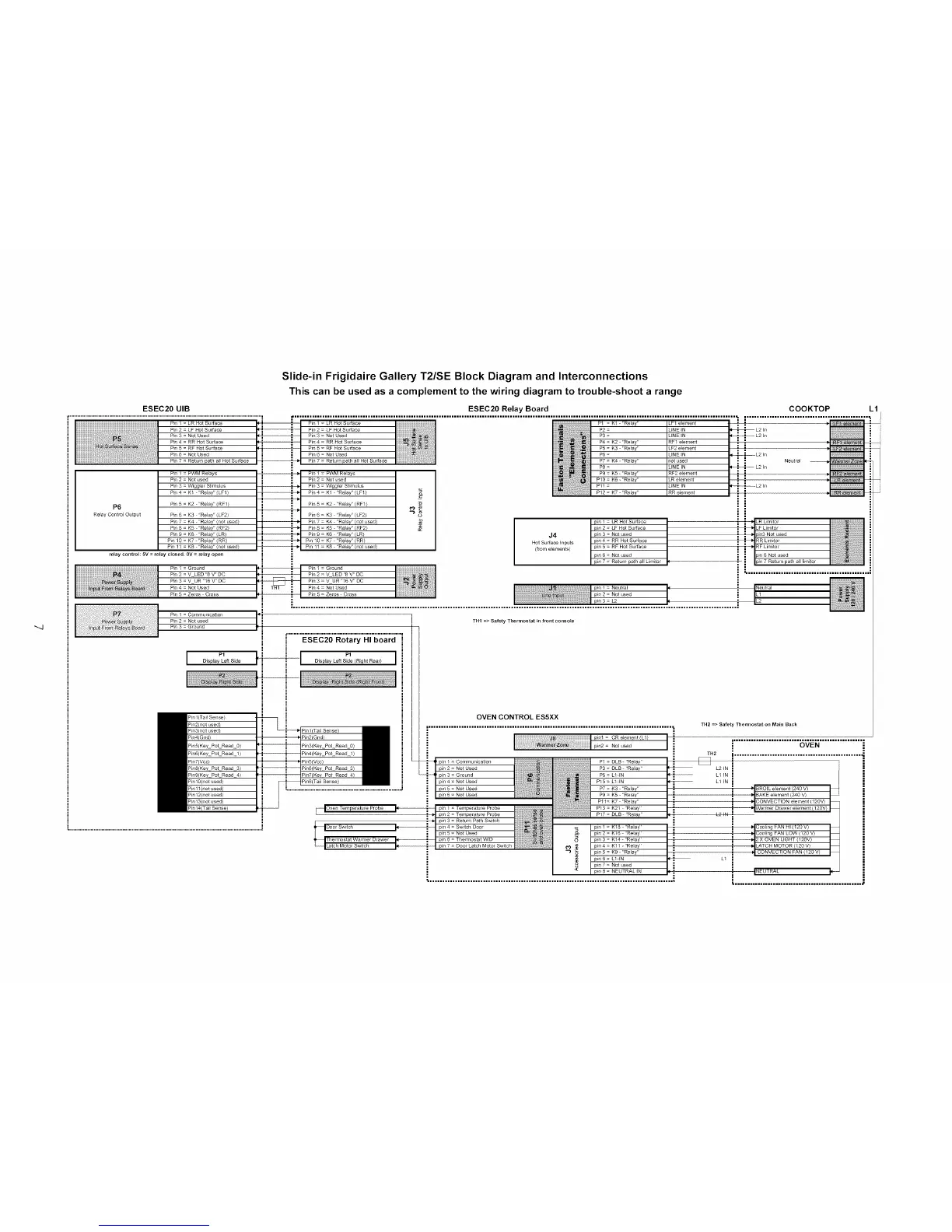
Slide-in Frigidaire Gallery T2/SE Block Diagram and Interconnections
This can be used as a complement to the wiring diagram to trouble-shoot a range
ESEC20 UIB ESEC20 Relay Board COOKTOP L1
..............................................................................................................................._ ............................................................................................................................................................................... , .................................................. ; J
P_n I = LR Hot Surface ! ; Pm I = LR Hot surface PI = KI - 'Re_ay' LFI e_ement _ .
Pin2=LFHo_Surface ;! P2 = UNEIN • _ =" L2in =
Pin 3 = NO_ Used _i= P3 = LINE IN __ ,J_ L2 In ,=
Pin4=RRHotSurfa_ _: P4=K2 "Relay" RFlelement _ 1" ;
P_n 5 = RF Hot Surface ; P5 = K3 - "Re_ay" LF2 e_ement
[
Pin 6 = Not Used P6 = LINE IN _ ; L2 In
P_n 7 = Re_urn path al_ HO_ Surface P_n 7 = Re_urn path a_ HO_ Surface P7 = K4 - "Relay" no_ used Neutral
P8= UNEIN _ _ -- L21n
P_n 1 = PWM Relays P9 = K5 - "Relay" RF2 element
Pin 2 = Not used P10 = K6 - "Relay" LR element
Pll = LINE IN
P12 = K7 _ "Relay" RR e_ment
P_n 3 = W_gg_er Stimulus
P_n 4 = K1 - "Relay" (LF1)
P6 P_n 5 = K2 - "Relay" (RF1)
Re!ay Contror Output P_n 6 = K3 'rRelay'r (LF2)
Pin 7 = K4 "Relay" (not used)
P_n 8 = K5 - "Relay" (RF2)
P_n 9 = K6 'rRelay'r (LR)
Pm 10 = K7 -"Relay" (RR)
P_n 11 = K8 'rRelay'r (not used)
relay control: SV = relay closed. OV = _lay open
Pin I : Ground
P_n 2 = VLED Ir8 V Ir DO
P_n 3 = V UR "16 V 'r DO
P_n 4 = Not Used
P_n 5 = Zeros Cross
; P_n 2 = LF Hot Surface
P_n 3 = NO_ Used
=; P_n 4 = RR Hot Surface
Pm 5 = RF Hot Surface
i Pin 6 - Not Used
P}n 1 = PWM Re_ays
Pin 2 = Not used
P_n 3 = _,%r_gg_er Stimulus
P_n 4 = K1 - "Relay" (LF1)
P_n 5 = K2 - "Relay" (RF1)
P_n 6 = K3 'rRelay'r (LF2)
Pin 7 = K4 - "Re_a¥" (not used)
P_n 8 = K5 - "Relay" (RF2)
P_n 9 = K6 'rRelay'r (LR)
Pm 10 = K7 - "Re_ay" (RR)
Pin 11 = K8 'rRelay'r(not used)
J4
Not Surface Inputs
(hom elements)
p_n I - LR Hot Surface
p_n 2 = LF Hot Surface
pin 3 = Not used
pm 4 = RR Hot Surface
pin 5 = RF Hot Surface
pm 6 = Not used
p_n 7 = Re_urn path al_ L[mr_or
.....................IJ
Pin 2 : Not used
Pin 3 : Ground
ESEC20 Rotary HI board
I P' P' IDisplay Left Side Display Left Side (Right Rear}
Pinl(Tai Sense)
Pro2 not used_
Pm3(not used}
P_n4(Gnd)
P_n5(Key Pot Read 0)
P_n6(Key PoLRead 1)
P_n7(Vcc)
Pm8(Kev Pot Read 3'
Pm9 Key Pot Read 4_
P_nl0(not used)
Pro11 not used_
P_n12(not used)
P_n13(not used)
P_n 14(Ta_ Sense)
THI => Safety Thermostat in front console
OVEN CONTROL ES5XX
....i............ .i
pin = Communicalion _ 1
at_on _ _,
• _ P5 - LldN
; pin 4 = Not Used P15= L1 IN _--
• _ _ I.
[_lOven Temperature Probe _ pin 1 = Temperature Probe
pm 2 = Temperature Probe
p_n 3 : Return Path Switch
Door Sw_tch p_n 4 = Sw_tch Door
pin 5 = Not Used
I hermostat Wa_l_e r Drawer pin 6 = The_l_ostat '¢v'/D
p_n 1 = K18 _ "Relay" |i
pin 2 = K16 "Relay" •
p_n 4 = K11 "Relay"
p_n 5 = K9 - "Relay"
pin 7 = Not used
pm 8 = NEUTRAL _N
1142 => Safety Themlostat on Main Back
i..........................5;_i_..................
TH2 I..................................................
L2 IN i
L1 IN -=
L1 IN
BROIL element 240 V)
i|I'=_I ••1'_Cooling FAN HI (120 V)
L1
 Loading...