Co
ESEC20 UIB
Pm 2 = LF Hot Surface
Pin 3 = NO_ Used
Pin 4 = RR Hot Su,rfa_
Pm 5 = RF Hot Surface
Pin 6 = Not Used
Pin 7 = Return pa_l a_ Hot Surface
Pin 1 = P_'_&4 Relays
Pm 2 = Not used
Pin 3 - _AJggler Stimulus
Pin 4 - K1 - "Re_ay" (LR}
Pin 5 = K2 "Re_ay" (RR2)
Pm 6 = K3 - "Re_ay" (RF2)
Pin 7 = K4 "Re_ay" (not used)
Pin 8 - K5 - "Re_a¥" (LF1)
Pin 9 = K6 _ "Relay" (LF2)
Pin 10 = K7 "Re_ay'r(RR1)
Pin 11 = K8 _ "Relay" (RF1)
_lay control: SV = relay closed. OV = relay open
Pin 1 = Ground
Pm 2 = VLED "8 V" DO
Pin 3 = V UR "16 V' DC
Pin 4 = Not Used
Pin 5 = Zeros - Cross
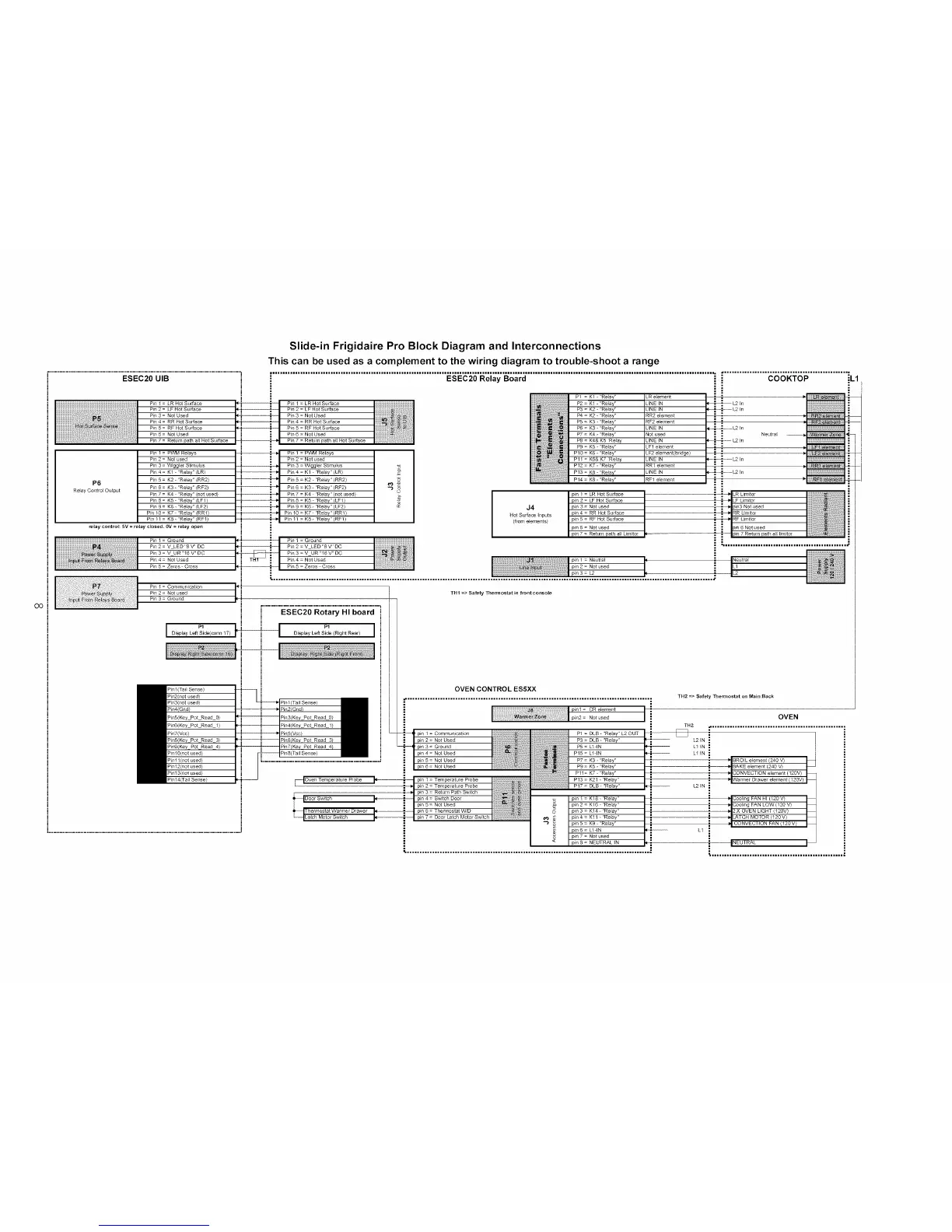
Slide-in Frigidaire Pro Block Diagram and Interconnections
This can be used as a complement to the wiring diagram to trouble-shoot a range
• ................................................................................................................................................................................ • ..................................................
ESEC20 Relay Board COOKTOP _L1
P6
Relay Control Output
Pm 1 = LR Hot Surface
Pm 2 = LF Hot Surface
Pin 3 = Noi Used
-" Pin 4 = RR Hot Surface
i Pm 5 = RF Hot Surface
i Pin 6 = NO_ Used
Pin 7 = Return path a_ Hot Surface
Pin 1 = P_N&4 Relays
Pm 2 = Not used
Pin 3 = Wiggler Stimulus
Pin 4 = K1 - "Relay" (LR}
Pin 5 = K2 "Re_ay"(RR2)
Pm 6 = K3 - "Re_ay" (RF2)
Pin 7 = K4 "Re_ay" (not used)
Pin 8 = K5 - "Relay" (LF1}
Pin 9 = K6 - "Relay" (LF2)
Pin 10 = K7 "Relay"(RR1)
! : . Pin 11 = K8- "Relay" (RF1)
i
Pin 1 = Ground
Pm2=V LED "8 V" DO
Pin 3 = V UR "16 V" DO
Pin4 = Not Used
!
....................[i
Pin 2 = Not used
Pin 3 : Ground
I
i ............."E'_i_'_'_'_"i_ot;;_;"i4i'"bo'_'/_i....
!
Display Left Side(corm 17) Display Left Side (Right Rear)
I
pin 2 =
J4 pin3=
Hot Surface Inputs pin 4 =
(from elements) p_n 5 =
P5 = K3 'rRelay'r
P6 = K3 -"Relay"
P7 = K4 - "Relay" Neutra_
P8 = K4& K5 Relay
P9 = K5 -"Relay"
P11 = K6& K7 Relay
P12 : K7 "Relay" _R1 e_ement
PI3 : K8 - "Re_a¥" JNE IN _L -L2 In
PI4 : K8 -"Relay" _Ff e_ement :
!
kRHotserface ! ; _ kRkm o
LF Hot Surface [ l _ LF Lim_tor
Not used ; ) p_n3 NO used
RR Hot Surface i _ RR Lim_tor
RF Hot Surface -" ) RF Um_tor
Not used _ pin 6 Not used
Return path a_ Lim_tor th a_l lim_tor
• i................................................. ,_
Nkk_utr_i
_ L_
Bnl (Ta_l Sense}
Door Switch
hermostat Warmer Drawer
_Sw_lch
THI => Safety The_ostat in front console
OVEN CONTROL ES5XX
= Communication
Not Used
Ground
Not Used
Not Used
- Temperature Probe
p_n 2 = Temperature Probe
Return PatI_ Sw_tch
Switch Door
Not Used
Thermostat W/D
P1 = DLB - "Relay" L2 OUT
P5 = LlqN
P15 = LldN
P9 : K5-"Relay"
P11= K7-"Relay"
P13 : K21-"Relay"
i
= K18-"Relay"
pin2= K16 'rRelay'r
pin3= K14-"Relay"
pin 4 = Kll -"Relay" i
K9 'rRelay'r
LlqN
Notused
TH2 => Safety The_ostat on Main Back
OVEN
TH2
L21N !
L1 IN i
Li IN
T" BROIL e_emen (240 V)
i BAKE element (240 V)
!
_}I CONVECTION element (120V}
L2 IN
i _v_ Coo_ing FAN HI 020V}
Coo_ing FAN LOW ( 120 V)
2X OVEN LIGHT (120V)
_ LATCH MOTOR (120 V)
kl
INEUTRAL
 Loading...