Section 3 Service and Testing Electrical System
3-7
Starting and Testing Control
The control at power up will display a “PF” code, that
shows the control has received power from the
junction box and is awaiting a command. The first check
is to press the START/CANCEL pad, this will clear the
“PF” code, and the control will be ready for operation.
The next check for the control with “PF” in the display, is
to open and close the door. This opens the door switch,
the control senses the power loss from the switch, and
the “PF will clear from the display” and the control will
be ready for operation.
If after either of these tests the “PF” still remains in the
display, the control is not reacting to commands and to
the presence of power from the door switch. The
corrective action is to replace the control.
If while a cycle is in operation, and a “PF” code appears
in the display, this is an indication the microprocessor on
the control has experienced a power loss. The control
system needs to be checked for shorts or damage that
could effect the control. Replacing the main control is
the last resort for this condition.
Water/Service Test
The dishwasher can be tested by use of the water/ser-
vice test. This test allows the dishwasher to operate all
the electrical components in a short cycle of 382
seconds. This test will not give failures codes or display
if a component has or will fail, but will in most cases,
give you time to do electrical checks of the different
component. By running this test, all of the components
are operated in order as they will in a wash cycle so
operation can be monitored.
The water/service test is a special function initiated from
the power failure mode or idle mode.
While in power failure or idle mode - Simultaneously
press the NO HEAT DRY and START/CANCEL pads for
1-1/2 seconds. The dishwasher will then step through
the test cycle per the chart below. Pressing the START/
CANCEL pad will advance the dishwasher to the next
step. (See Figure 3-9)
STEP
TOTAL TIME (SEC)
WATER VALVE
CIRCULATION PUMP
DRAIN MOTOR
HEATER
DISPENSER
VENT*
WASHING LED
DRYING LED
RINSE AGENT LED
CLEAN LED
1FILL 36 1000001000
2 WASH/HEAT/ DISP 60 0 1 0 1 101000
3 PAUSE 0.6 0 0 0 1 0 0 1 0 0 0
4 WASH/HEAT 75 0 1 0 1 0 0 0 0 0 0
5 WASH/HEAT/DISP 60 0 1 0 1 1 0 0 0 0 0
6DRAIN 60 0010010000
7DRY 90 001X000100
TOTAL 382 0 0 1 1
X - denotes selectable option
CLEAN LED stays on unitl door is opened or cycle is selected
* VENT is actuated on models with active vent system
Figure 3-9. Water /Service Test Chart
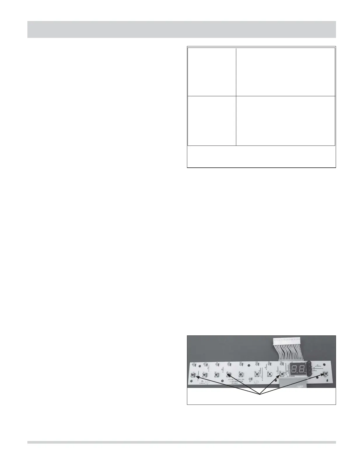
Selector Switch
The display board is used to program the control for
the desired wash cycle and options. This display board
is a circuit board with microswitches for each cycle and
options. This board also has indicator lights and two 7
segment displays to show time remaining and cycle
status. The display board has a wire ribbon to connect it
to the control. (See Figure 3-10)
To check the selector switch:
With the wire ribbon connected to the control, press a
cycle pad. The light for that pad should light after 10 to
15 seconds. The light will then go out, proceed to the
next pad and repeat until all pads have been checked.
The final check will be to select a cycle and press the
START/CANCEL pad to make sure the control will accept
the start command from the display board. If the unit
starts or the time starts to count down, the display
board has properly programmed the control.
Tactile Switches
Figure 3-10.
 Loading...