Do you have a question about the Frigidaire FGGC3645KSC and is the answer not in the manual?
Details physical dimensions, cutout sizes, and product measurements for installation.
Specific regulations and requirements for gas appliance installation in Massachusetts.
Essential safety precautions and warnings for installation and operation.
Guidelines for cabinet construction, dimensions, and required clearances for installation.
Procedures for mounting cooktops above electric built-in ovens.
Specifies the recommended location for the electrical outlet.
Requirements for natural and LP gas supply, including conversion.
Steps for connecting the gas supply, installing regulator, and checking leaks.
Procedures for checking gas connections for leaks after installation.
Details electrical supply needs and proper grounding procedures.
Instructions for adjusting burner low settings and final operation checks.
Schematics illustrating the electrical connections for the cooktop.
| Type | Gas |
|---|---|
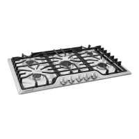
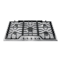
| Number of Burners | 5 |
| Ignition Type | Electronic |
| Surface Material | Stainless Steel |
| Control Type | Knobs |
| Fuel Type | Natural Gas |
| Color | Stainless Steel |
| Burner Type | Sealed |
| Installation Type | Built-In |
| Gas Type | Natural Gas |
| Convertible to LP | Yes |
| Width | 36 inches |
| Warranty | 1-year full warranty |
| Depth | 21.75 inches |