tilecabinet.If backof rangewill not beflushwith
the wall (thelocationoftheoutletmaynotallowthe
rangeto bepositionedagainstthewall),drawa lineon
thefloorwherethebackedgeoftherangewill be.Now
installanti-tipbrackets(see"Anti-tipBrackets
Installation",page10).
tf rangewill not beinstalledagainstacabinet,
moverangeintofinalposition.Drawalineonthefloor
alongbothsidesoftherange,tf backof rangewill not
beflushwith the wall (thelocationoftheoutletmay
notallowtherangeto bepositionedagainstthewall),
drawalineonthefloorwherethebackedgeof the
rangewillbe.Nowinstallanti-tipbrackets(see"Anti-tip
BracketsInstallation",page10).
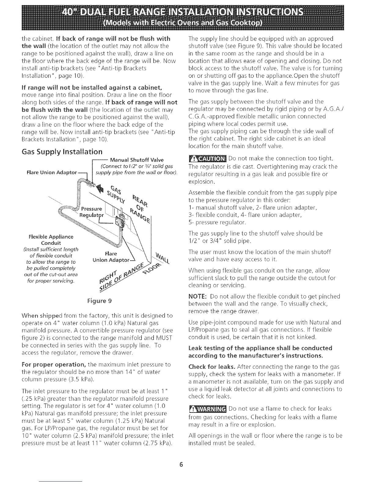
Figure9
Whenshippedfromthefactory,thisunitisdesignedto
operateon4" watercolumn(1.0kPa)Naturalgas
manifoldpressure.Aconvertiblepressureregulator(see
figure2)isconnectedtotherangemanifoldandMUST
beconnectedinserieswiththegassupplyline. To
accesstheregulator,removethedrawer.
Forproperoperation,themaximuminletpressureto
theregulatorshouldbenomorethan14"ofwater
columnpressure(3.5kPa).
Theinletpressureto theregulatormustbeat leastI "
(.25kPa)greaterthantheregulatormanifoldpressure
setting.Theregulatorissetfor4" watercolumn(I.0
kPa)Naturalgasmanifoldpressure;theinletpressure
mustbeatleast5" watercolumn(1.25kPa)Natural
gas.ForLP/Propanegas,theregulatormustbesetfor
10"watercolumn(2.5kPa)manifoldpressure;theinlet
pressuremustbeatleast11" watercolumn(2.75kPa).
Thesupplylineshouldbeequippedwithanapproved
shutoffvalve(seeFigure9).Thisvalveshouldbelocated
inthesameroomastherangeandshouldbeina
locationthatallowseaseofopeningandclosing.Donot
blockaccesstotheshutoffvalve.Thevalveisforturning
onorshuttingoff gastotheappliance.Opentheshutoff
valveinthegassupplyline.Waitafewminutesforgas
tomovethroughthegasline.
Thegassupplybetweentheshutoffvalveandthe
regulatormaybeconnectedbyrigidpipingor byA.G.A./
C.G.A.-approvedflexiblemetallicunionconnected
pipingwherelocalcodespermituse.
Thegassupplypipingcanbethroughthesidewallof
therightcabinet.Therightsidecabinetisanideal
locationforthemainshutoffvalve.
Donotmaketheconnectiontootight.
Theregulatorisdiecast.Overtighteningmaycrackthe
regulatorresultinginagasleakandpossiblefireor
explosion.
Assembletheflexibleconduitfromthegassupplypipe
tothepressureregulatorinthisorder:
1-manualshutoffvalve,2-flareunionadapter,
3-flexibleconduit,4-flareunionadapter,
5-pressureregulator.
Thegassupplylinetotheshutoffvalveshouldbe
1/2"or3/4"solidpipe.
Theusermustknowthelocationofthemainshutoff
valveandhaveeasyaccessto it.
Whenusingflexiblegasconduitontherange,allow
sufficientslackto pulltherangeoutsidethecutoutfor
cleaningorservicing.
NOTE:Donotallowtheflexibleconduittogetpinched
betweenthewallandtherange.Tovisuallycheck,
removetherangedrawer.
Usepipe-jointcompoundmadefor usewithNaturaland
LP/Propanegastosealallgasconnections.Ifflexible
conduitisused, be certain that it is not kinked.
Leak testing of the appliance shah be conducted
according to the manufacturer's instructions.
Check for Jeaks. After connecting the range to the gas
supply, check the system for leaks with a manometer. If
a manometer is not available, turn on the gas supply and
use a liquid leak detector at all joints and connections to
check for leaks.
Do not use a flame to check for leaks
from gas connections. Checking for leaks with a flame
may result in a fire or explosion.
All openings in the wall or floor where the range is to be
installed must be sealed.
 Loading...