34
Connecting the hosepacks to the cooling unit
Safety
WARNING!
An electric shock can be fatal.
Before starting the work described below:
► turn the power source mains switch to the "O" position
► disconnect the power source from the mains
► ensure that the power source remains disconnected from the mains until all work has
been completed
Connect the inter-
connecting hose-
pack coolant
hoses to the cool-
ing unit (TS/TPS
4000/5000)
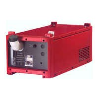
NOTE!
For TS 4000 / 5000, TPS 3200 / 4000 / 5000 power sources, the power source (1) must
be connected to the cooling unit using an interconnecting hosepack.
Plug in and secure the interconnecting
hosepack strain-relief device (1) in the
opening provided on the base of the
trolley (see trolley operating instruc-
tions)
Connect the red hose from the inter-
connecting hosepack (2) to the coolant
return connection on the cooling unit
Connect the blue hose from the inter-
connecting hosepack (3) to the coolant
flow connection on the cooling unit
Connecting the
welding torch
coolant hoses to
the cooling unit
(TPS 2700)
(1)
(2)
(3)
1
2
3
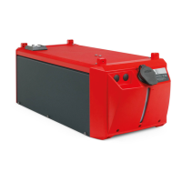
NOTE!
A water-cooled welding torch with an
external coolant connection is required
for welding with a TPS 2700 power
source and cooling unit.
The coolant flow and return connections
must be moved to the front of the cooling
unit (see "Fitting coolant connections to
the front of the unit").
Connect the red welding torch hose
(2) to the coolant return connection
on the cooling unit
Connect the blue welding torch hose
(3) to the coolant flow connection on
the cooling unit
1
2
 Loading...