To assemble the mower proceed as follows:
1. Unbolt the wheel arms and discard the mounting bracket.
2. Separate the wheel arms and remove the hardware bag secured between them.
3. IMPORTANT: Remove the belt shields to inspect around the belt area and
under the gearbox central plate to be sure the area is clear of packing material
such as blocks of wood, paper, etc.
4. Bolt the wheel arm assemblies to the mower deck with the flat washer and locknuts.
There is no difference between left/right or front/rear. Be sure both assemblies are
securely mounted.
5. Assemble each wheel to the yokes with one M14x140 bolt and one inner bushing.
Tighten down snugly. The wheel should turn freely but have no side to side
movement.
6. Replace the belt shields.
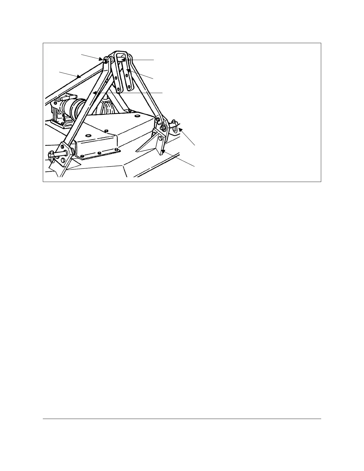
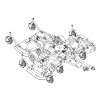
7. Bolt up the top hitch arms (see #5, fig. 2 & 3) to the outside of the rear support
plates on the rear of the mower (see #8, fig. 3).
8. Bolt up the top hitch supports (see #3, fig. 2 & 3) to the inside of the linking plates
(see #6, fig. 2) that are already bolted to the outside of the front support plates (see
#7, fig. 2).
9. Bolt up the top hitch plate (see #2, fig. 2 & 3) with the M16x140 bolt. It should be
bolted as follows: bolt, top hitch support, top hitch arm, top hitch plate, spacer, top
hitch plate, top hitch arm, top hitch support, locknut. Tighten the locknut down
securely, the top hitch plate should be able to swivel 360°.
10.Grease, wheel arms, and spindles. Check the gearbox for oil. It should be
approximately ½ filled.
11.Install driveline and ensure it has at least 2” from bottoming out in its shortest
working position and has the minimum 6” overlap in its longest working position.
Refer to Section 4.06
1
of this manual, if it is determined that the driveline is too long
GROOMING MOWERS OPERATOR’S MANUAL
GENERAL INFORMATION 6 FRONTIER
1
See Section 4.06 - Driveline, for instructions on how to determine correct driveline length and
7
6
3
1
2
4
5
Fig. 2
1. inner spacer
3. top hitch support
4. bolt
6. linking plate
7. front support plate
5. top hitch arm
2. top hitch plate