Optional Equipment 13
5WPMAN0148 (Rev. 5/16/2008)
OPTIONAL EQUIPMENT
SINGLE TAILWHEEL KIT 5WP1001533
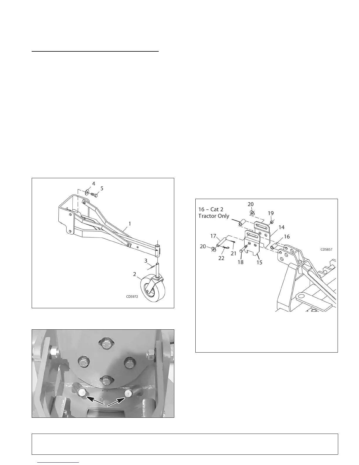
Assemble Tailwheel (Figure 10)
NOTICE
Floating links must be used with tailwheel to
avoid equipment damage.
Tailwheel kit will not function properly when
used with Quick Hitch.
Remove round retainer plate and hardware from rear of
tilt turntable of rear blade (refer to Figure 5).
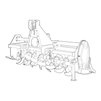
NOTE: Point drop pins in tilt turntable towards center of
unit (Figure 11) before attaching tailwheel tube assem-
bly.
Figure 10. Tailwheel Assembly
Figure 11. Drop Pin Position
Attach tailwheel tube assembly (1) to rear of tilt turnta-
ble and secure with cap screws (5) and hardened flat
washers (4) from turntable. Torque cap screws to 170
lbs-ft. (231 N-m).
Attach yoke assembly (2) to tailwheel tube and secure
into position with spirol pin (3).
Assemble Floating Link (Figure 12)
Attach right and left floating link brackets (14, 15) with
offset to the inside on each side of the A-frame. Place
sleeve (16) in forward hole and secure assembly into
position using two cap screws (18) and lock nuts (19)
as shown in Figure 12.
NOTE: When attaching to tractor, install clevis pin (17)
into floating links using two 3/4" washers (20), one cot-
ter pin (21), and hair pin (22) as shown.
Figure 12. Floating Link Installation
Adjust Tailwheel Assembly
Set blade cutting edge 1/2" (13 mm) above the ground
with the tractor 3-point hitch. Adjust tail wheel until tire
is on the ground and the top link pin is centered in the
floating link slot. Fine tune the grading height by raising
or lowering the 3-point hitch.
1. Tailwheel
tube assembly
2. Notat yoke assembly
3. 3/8" Spirol pin
4. 5/8" Hardened flat washer
(from turntable)
5. 5/8 NF x 1-1/2" Cap screw
(from turntable)
14. Right floating link
15. Left floating link
16. Sleeve .78 x 1.00 x 2.00"
17. Clevis pin .75 x 4.38"
18. 3/4 NC x 4-1/2" Cap
screw GR5
19. 3/4" NC Lock nut
20. 3/4" Flat washer
21. 3/16 x 1-1/2" Cotter pin
22. 5/32" Hair pin cotter