EasyManua.ls Logo

Frontier wc1105 User Manual

Frontier wc1105
24 pages
To Next Page IconTo Next Page
To Previous Page IconTo Previous Page
Page #9 background image
7
INSPECTION AND SET-UP
Follow the instructions in the lubrication section of this manual to make sure the chipper
is greased properly. The initial grease is applied at the factory, but a routine maintenance
schedule is the user’s responsibility.
Check all bolts and nuts to make sure everything is tight. All hardware is checked at the fac-
tory, but sometimes it will vibrate loose during shipment. Also check all fasteners periodically
between uses. A wood chipper produces high vibration levels which can cause hardware to
loosen.
Check the position of the knives in relation to the chip anvil. The recommended setting is
1/32” (.8mm) between the anvil and the closest knife. You may notice the rotor has a slight
wobble which will cause some of the knives to run closer than others. This is normal. See
page 9 for instructions on adjusting the anvil depth.
Check the chip chute locking device to make sure it locks the chute securely into position
when the handle is in the locked position. This adjustment is also made at the factory but
needs to be readjusted after the chute is “worn in”.
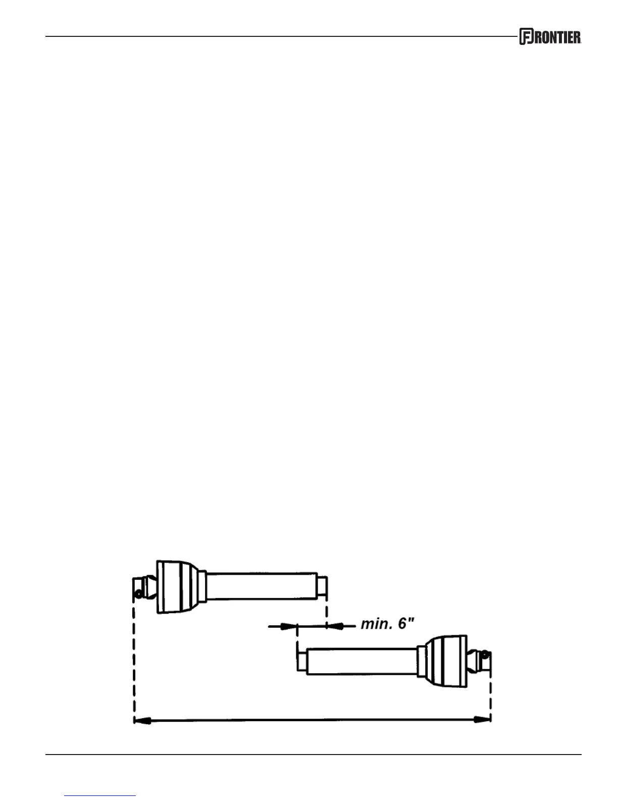
Check the length of the PTO shaft. Some tractor 3-point hitch arms are shorter and require
a shorter PTO shaft. To determine whether your shaft needs to be cut down to t you will
need to connect the 3-point arms to the chipper, connect the PTO shaft to both the tractor
and chipper, and slowly raise the 3-point hitch. Watch closely to make sure that the PTO
shaft does not fully retract. If it does, you will need to remove it and cut it down accordingly.
If the PTO shaft is not tted properly it can “bottom out” and cause damage to the PTO shaft
or the chipper. Also check the PTO to make sure the tubes overlap at least 6 inches (15cm)
(see illustration below) when the chipper is in the operating position. (sitting level on the
ground)
Question and Answer IconNeed help?

Do you have a question about the Frontier wc1105 and is the answer not in the manual?

Frontier wc1105 Specifications

General IconGeneral
BrandFrontier
Modelwc1105
CategoryChipper
LanguageEnglish

Summary

Introduction

Intended Use

Specifies that Frontier Chippers are designed for natural, untreated wood only.

Serial Number Location and Purpose

Explains where to find the serial number and its importance for service and tracking.

Technical Specifications Overview

Presents detailed technical specifications for various WC models in a comparative table.

Safety Information

General Operational Safety Warnings

Crucial warnings about operating the machine, personal safety, clothing, and bystander protection.

Rotating Driveline Hazards

Details the severe risks of driveline entanglement and required safety measures.

Safety Decal Guide

Illustrates and explains the placement and meaning of all safety warning decals on the chipper.

Inspection and Set-up Procedures

Pre-Operation Checks and Adjustments

Covers essential checks: lubrication, bolt tightness, knife-anvil setting, chute lock.

PTO Shaft Length Verification

Instructions on how to verify PTO shaft length to prevent operational damage.

Operation and Adjustments

Chipper Startup Procedure

Step-by-step guide for safely starting the tractor and engaging the PTO-driven chipper.

Chipping Best Practices

Tips for feeding material, managing branches, and optimizing chipping with different wood types.

Chip Chute and Deflector Adjustment

Guidance on adjusting the chip chute rotation and deflector angle for chip trajectory.

Maintenance and Service

Drive Belt Maintenance

Instructions for checking belt tension and replacing the drive belts on the WC1105.

Knife and Anvil Care

Details on maintaining and adjusting chipper knives and the anvil for optimal performance.

Lubrication Guidelines

Bearing Lubrication Schedule

Provides instructions on greasing the chipper's bearings every 8 hours of use.

Warranty Details

Parts Identification

Base Assembly Parts List

Lists all components and part numbers for the WC1105 base assembly with diagrams.

Main Assembly Parts List

Lists all components and part numbers for the WC1105 main assembly with diagrams.

Decals and Labels

Safety Decal Identification and Placement

Identifies all safety decals, their location, and corresponding item numbers for reference.