5. Installation
NOTE: Before installation, please inspect the unit. Be sure that nothing inside the package is
damaged.
Connect to Utility and Charge
Plug in the AC input cord to the wall outlet. The unit will automatically charge the connected
external battery even though the unit is off.
Connect External Battery
Step 1- Take away the cover of external battery terminal.
Step 2- Following battery polarity guide printed near the battery terminal!
Place the external battery cable ring terminal over the battery terminal.
RED cable to the positive terminal (+);
BLACK cable to the negative terminal (-).
WARNING! Please use the appropriate battery cable. Please refer to Important Safety
Warnings Section for the details.
Step 3- Tight the battery cables with the M5 nuts. Do NOT place anything between the flat
part of battery terminal and the battery cable ring terminal, or overheating may occur.
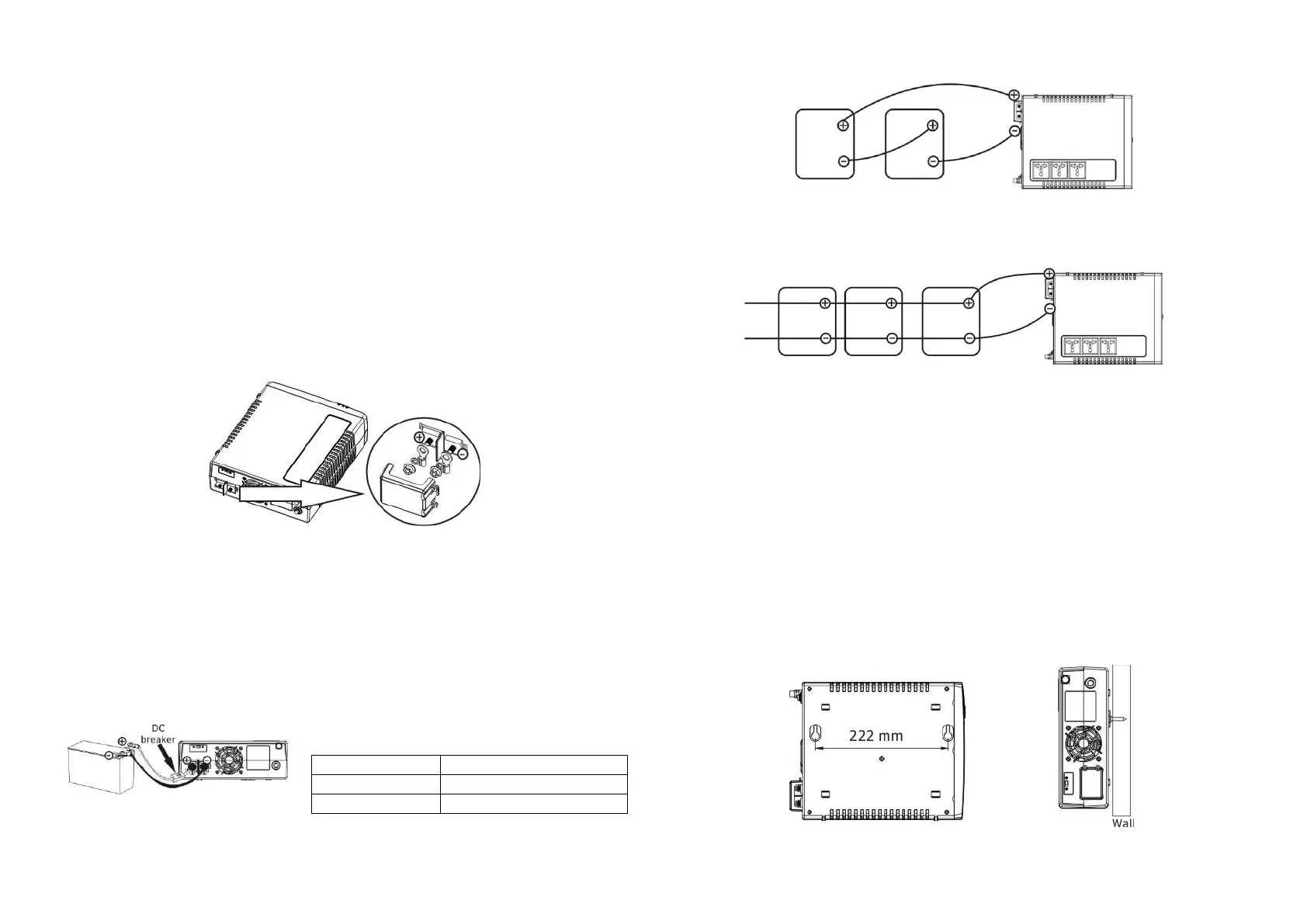
(See Fig. 1)
Fig.1 Battery cable connects to the inverter
Step 4- Install a DC Breaker in a positive battery line. The rating of the DC Breaker must be
according to the inverter's battery current (75 Amp). Keep the DC breaker off. (see Fig. 2)
Step 5- Connect battery cables to the external batteries.
Note: For the user operation safety, we strongly recommend that you should use tapes to
isolate the battery terminals before you start to operate the unit.
1) Single battery connection(Refer to Fig. 2): When using a single battery, its voltage
must be equal to the Nominal DC Voltage of the unit (see below Table 1).
2) Multiple batteries in series connection(Refer to Fig. 3): All batteries must be
equal in voltage and amp hour capacity. The sum of their voltages must be equal to the
nominal DC Voltage of the unit.
Fig 3
3) Multiple batteries in parallel connection(Refer to Fig. 4): Each battery's voltage
must be equal to the Nominal DC Voltage of the unit.
Fig 4
Step 6- Make sure to connect the polarity of battery side and the unit correctly.
Positive pole (Red) of battery to the positive terminal (+)of the unit.
Negative pole (Black) of battery to the negative terminal (-) of the unit.
Step 7- Put the covers back to the external battery terminals.
Step 8- Take the DC breaker on.
Mounting the Unit
The unit can be mounted to a wall surface. Please follow below steps:
1. Turn off the unit before mounting.
2. Select an appropriate mounting location. Use a horizontal line and the length of the line
must be 222 mm and mark the two ends on the wall. (see chart 1)
3. Drill two marks by screws.
4. Mount the unit by positioning the key-hole slots over the mounting screws.
(see chart 2)
Char 1 Chart 2
Nominal Battery DC Voltage
 Loading...