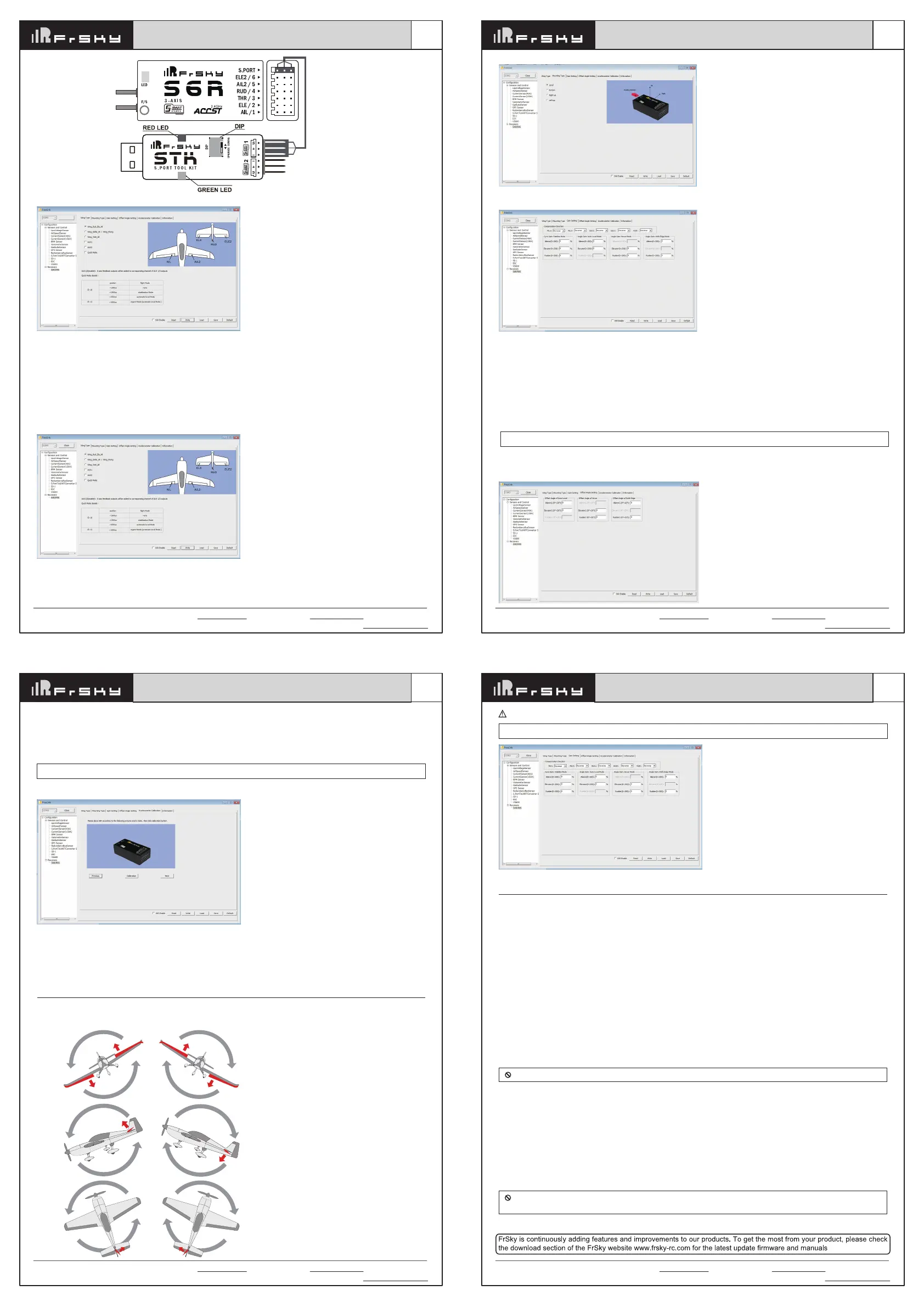
When the plane is rotated to left or right (Yaw),
rudders should have the correcting actions as
illustrated above.
When the plane is rotated left or right (Roll),
ailerons should have the correcting actions as
illustrated above.
When the plane is rotated up or down (Pitch),
elevators should have the correcting actions as
illustrated above.
Inspection of flight attitude
To ensure flight safety, checking the compensation direction of the model is strongly recommended.
Activating auto level mode will produce a strong deflection on AIL and ELE, which is used to check the response of aileron and elevator. Also,
activating Knife-edge and Hover mode will have the same reaction on the rudder.
The positive and negative values related to three-axis gyroscope and accelerometer make a total of six values that need to be acquired.
Please follow the on-screen instructions.
•
Click the “Calibration” button and wait until the YELLOW LED flashing, indicating the calibration on this orientation has been completed.
•
Repeat the above step five times (remaining 5 dimensions). Placing S6R/S8R in the required orientation, ensure all values (X, Y, Z, Mod) are
displaying 1.000 with the deviation of ±0.1.
•
Press “Write” to save the data on S6R/S8R when done.
Accelerometer Calibration
Note: Optional range is from -20° to 20°.
Offset Angle of Auto Level
The angle of roll and pitch could be adjusted on the channels related to aileron and elevator. Straight and Level flight could be realized.
Offset Angle of Hover
The nose-up angle could be adjusted on the channels related to aileron and elevator. Stationary hover could be realized in calm weather.
Offset Angle of Knife Edge
The angle of aileron and rudder could be adjusted on the related channels. Straight and level knif-edge flight could be realized.
Wing Type
Options of wing types: Wing_Rud_Ele_Ail——conventional model
Wing_Delta_Ail/Wing_Flying—— Delta/Flying wing
Wing_Vtail_Ail——V-Tail
AUX1: If selected, AIL2 function will be disabled on CH5
AUX2: If selected, ELE2 function will be disabled on CH6
Note: Optional range is from 0 to 200%. 0, 1, 2 refers to 0%, 100% and 200% respectively.
Offset Angle Setting
Due to the possible errors in minor installation and calibration, the function is designed to adjust the attitude of the model. Thus, the user could
achieve the best orientation when Auto Level, Hover mode and Knife-edge mode is activated.
The first part
Compensation direction: selecting the travel direction of AIL, AIL2, ELE, ELE2 and RUD. “+” means positive and “-” means negative.
The second part
Gyro gain: Stabilization Mode
The gain setting under stabilization mode chould be set on the channels related to aileron, elevator and rudder.
Angle Gain: Auto Level Mode
The gain setting under automatic level mode could be set on the channels related to aileron and elevator.
Angle Gain: Hover Mode
The gain setting under hover mode could be set on the channels related to elevator and rudder.
Angle Gain: Knife Edge Mode
The gain setting under knife edge mode could be set on the channels related to aileron and rudder.
Mounting type
Level, Buttom, Right and Left up options are available.
Gain Setting
FrSky Electronic Co., Ltd. www.frsky-rc.com Contact us : frsky@frsky-rc.com
Add: F-4,Building C, Zhongxiu Technology Park, No.3 Yuanxi Road, Wuxi, 214125, Jiangsu, China Technical Support: sales4tech@gmail.com
01140055
Version
1.0
Instruction Manual for FrSky S6R/S8R
FrSky Electronic Co., Ltd. www.frsky-rc.com Contact us : frsky@frsky-rc.com
Add: F-4,Building C, Zhongxiu Technology Park, No.3 Yuanxi Road, Wuxi, 214125, Jiangsu, China Technical Support: sales4tech@gmail.com
01140055
Version
1.0
Instruction Manual for FrSky S6R/S8R
FrSky Electronic Co., Ltd. www.frsky-rc.com Contact us : frsky@frsky-rc.com
Add: F-4,Building C, Zhongxiu Technology Park, No.3 Yuanxi Road, Wuxi, 214125, Jiangsu, China Technical Support: sales4tech@gmail.com
01140055
Version
1.0
Instruction Manual for FrSky S6R/S8R
After changing the compensation direction, make sure to check it again on the actual model.
Note: If the compensation direction is incorrect, please reverse the corresponding channel as illustrated below.
Under identical operating conditions, the value of each channel produced by the assigned switch in FrOS are opposite to that in
OpenTX. For exmaple, SW Up in FrOS is equal to SW Down in OpenTX.
Never operate the stick bound to CH12 during flight session. If so, it will trigger self-check and may cause the crash of the model.
Self-check
Attentions
•
Before self-check, please place the model on the groud (level surface).
•
When the model is flying, aerodynamic balance is more important than level attitude, which results in that the model flys at a constant altitude
with the nose slightly pointing up at low speed. To avoid the nose-diving of the model at high air speed, the user must insure that the model is
placed at a level or slightly-nose-up attitude during self-check.
•
Always install S6R/S8R straight and level in the model. If required, PC software could be used to adjust the angle of attack with the purpose of
realizing the required setting. If the values set by the user is bigger than average ones, we advise to recheck the installation orientation of
S6R/S8R.
Steps
•
Turn on the transmitter and ensure that Ail (CH1), ELE (CH2), RUD (CH4), AIL 2(CH5) and ELE (CH6) are in the neutral position.
•
Power on the model and start S6R/S8R self-check. Ensure the auto level angle of the gyro and the neutral position of gimbal. Please don’t touch/
move the model until self-check finishes, or it may corrupt the calibration settings created during the procedure.
•
Move the three-position sticks bound to CH12 three times in 3 seconds (up, mid, down). Then the BLUE LED will turn on, indicating self-check
procedure is initiated. After that, the corresponding parts on the model will move. At last, the BLUE LED will turn off, indicating self-check has
completed.
•
Move the sticks bound to CH1~CH6 (except the stick related to Thr) and check the channel output limits, ensuring that the signal outputs of
S6R/S8R will not damage the corresponding parts on the model. In the end, S6R/S8R will save the zero points of the gyro, auto level angle,
gimbal neutral position and servo channel limits.
Setup
•
Calibrate S6R/S8R with the PC software and install it into the model. Insure the settings of wing type and mounting type are identical to the
intended model installation.
•
Turn on the transmitter and reduce the value of servo endpoint setting. Ensure self-check mode will not damage the corresponding parts on the
model.
•
Assign a knob/slider to CH9, then real-time gain adjustment capabilities of S6R/S8R will be activated.
•
Assign three-position switches to CH10 and CH11 with the purpose of switching available flight modes.
•
Power on the model and check the deflection direction of each related parts on the model. Make sure the switch assigned to flight modes is
correct and the compensation direction of the gyro is set as intended on AIL, RUD and ELE.
•
Make a self-check for S6R/S8R if necessary. Disconnecting the power on S6R/S8R will not lose the set parameters.
FrSky Electronic Co., Ltd. www.frsky-rc.com Contact us : frsky@frsky-rc.com
Add: F-4,Building C, Zhongxiu Technology Park, No.3 Yuanxi Road, Wuxi, 214125, Jiangsu, China Technical Support: sales4tech@gmail.com
01140055
Version
1.0
Instruction Manual for FrSky S6R/S8R
1. Open: Gives the PC software access to S6R/S8R configuration data.
2. Read: Retrieves the stored S6R/S8R data to be edited in the PC software.
3. Write: Stores the setted data on S6R/S8R.
4. Load: restore the settings into the file you saved before.
5. Save: save all settings to one file.
6. Default: Returns all PC software settings to the factory defaults.
7. SXR Enable:Enable/Disable the stabilization function
Configuration parameters
The configuration parameters are listed on the top of the interface: Wing type, Mounting Type, Gain Setting, Offset Angle Setting,
Accelerometer Calibration
The menu screen on the home page is displayed below:
Open
STABILIZATION
 Loading...