EasyManua.ls Logo

FrSky TD SR10 User Manual

FrSky TD SR10
15 pages
To Next Page IconTo Next Page
Page #1 background imageLoading...
Page #1 background image
Instruction Manual for TD R10 & TD SR10 Dual-Band Receivers
FrSky Electronic Co., Ltd. www.frsky-rc.com Contact us : frsky@frsky-rc.com
Add: F-4,Building C, Zhongxiu Technology Park, No.3 Yuanxi Road, Wuxi, 214125, Jiangsu, China Technical Support: sales4tech@gmail.com
Introduction
The Tandem dual-band receivers are unlike any other FrSky 2.4Ghz or 900Mhz receivers, they work
simultaneously at both 2.4Ghz and 900Mhz frequencies. That means Tandem receivers provide not only the low
latency signal and long-range control but also benefit from the enhanced level of high reliability and
anti-interference performance.
The Tandem series receivers adopt the triple antenna design that provides multi-directional wide coverage for the
remote signal. The data (Power & Signal related) under unusual status during the flight can be recorded by
Tandem receivers through a built-in black box module.
The configurable 10 channel ports are a big feature of TD R10 & TD SR10, each channel port can be assigned
as PWM, SBUS, FBUS, or S.Port. With the FBUS protocol, the TD receivers can open up the possibility of
seamlessly pairing with multiple telemetry devices (Neuron ESC, Advance Sensors, etc.) as well as simplifying
the build setup.
ADV Stabilizer (TD SR10)
The TD SR10 offers an ADV Stabilizer function which is an upgrade over the original classical gyroscope
stabilization modes. The ADV Stabilizer offers an advanced mode that provides more programmable stabilized
channels and flexibility.
The classical stabilization mode has been enhanced with 5 additional stabilization channels, providing pin
mapping to each channel in the multiple flight modes like Stabilization, Auto-Level, Hover, and Knife-Edge with
an airplane model.
In the advanced stabilization mode, all the output pins are configurable for stabilization and additional advanced
features such as Stab file sharing, programmable parameters, developer access, etc.
The advanced stabilizer feature incorporates high-precision telemetry sensors to monitor altitude, vertical speed,
etc. This ADV feature is an additional benefit compared to using a regular S series stabilization receiver.
Overview
2.4G Antenna
2.4G Antenna
900M Antenna
AIN2
(Upgrade)
14.7mm
26.3mm
46.5mm
10
9
TD SR10
10/24CH Telemetry & Stabilization
Specifications
● Frequency: 2.4GHz & 900MHz
● Dimension: 46.5×26.3×14.7mm (L×W×H)
● Weight: 16.6g
● Operating Voltage: 3.5-10v DC
● Operating Current: ≤180mA@5V
● Compatibility: Tandem series transmitter & TD protocol capable RF module
Voltage Measurement Range via AIN2 (External device): 0-35V (Battery Voltage Divider Ratio: 1:10)
● Triple 2.4G/900M Antenna
- 2×External 2.4G antenna (IPEX1)
- 1×External 900M antenna (IPEX1)
10
9
10/24CH Long Range & Telemetry
TD R10
Question and Answer IconNeed help?

Do you have a question about the FrSky TD SR10 and is the answer not in the manual?

FrSky TD SR10 Specifications

General IconGeneral
Frequency2.4GHz
Channels10
TelemetryYes
Operating Voltage3.5V to 10V
PortsSBUS, S.Port

Summary

Introduction and Key Features

ADV Stabilizer Functionality

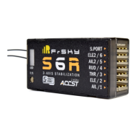
Discusses the ADV Stabilizer for enhanced gyro stabilization with programmable channels.

Receiver Overview

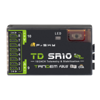
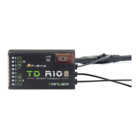
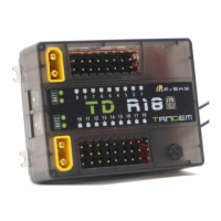
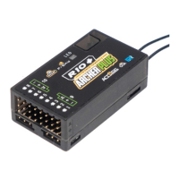
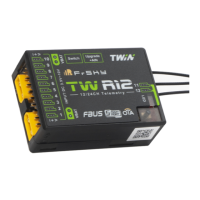
Visual layout and physical dimensions of the TD R10 and TD SR10 receivers.

Technical Specifications

Lists operating frequency, dimensions, weight, voltage, and compatibility details.

Product Features and Status Indicators

Core Product Features

Highlights dual-band operation, stabilization, black box, voltage sensor, and OTA updates.

LED Status Interpretation

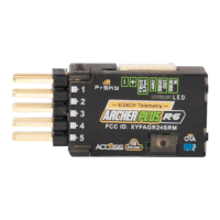
Explains the meaning of Green, Blue, and Red LEDs for binding and operational status.

Receiver Registration and Binding

Step-by-step guide for registering and automatically binding the receiver to the transmitter.

IMU Mode and Stabilization Setup

IMU Mode Configuration Options

Details OFF, BASIC, and ADV modes for the stabilization module via radio or PC.

ADV Stabilization Activation

Enabling ADV config for advanced self-stabilizing mode through the Upgrade/S.Port interface.

Advanced Stabilization Functions

CaliHorizontal Function

Enables horizontal plane calibration for ADV mode stabilization.

Independent Stabilizing Systems

Configuration for two independent stabilization systems (CH1-6 and CH7-11).

Stabilization Function Basic Guide

Steps for enabling stabilization, calibrating the gyroscope, and connecting servos.

Gyroscope Sensor Calibration

Gyro Calibration Tool Usage

Accessing and using the SRX Calibration tool for gyros and accelerometers.

Gyroscope Calibration Procedure

Step-by-step guide for calibrating the device's 6 surfaces on a flat surface.

Model Integration and Configuration

Servo Connection to Model

Connecting servos to receiver ports according to the Channel List.

Mixer and Radio Switch Setup

Setting up mixer channels and radio switches for flight modes.

Flight Mode Configuration and Tuning

Wing and Mounting Type Selection

Determining wing type and mounting configuration for stabilization.

Gain and Offset Settings

Configuring gains and offsets for Stab, Auto-Level, Hover, and Knife-Edge modes.

Flight Attitude Verification

Checking servo response in Auto-Level mode and inverting channels if necessary.

Flight Compensation and Output Check

Correcting Flight Control Actions

Ensuring correct aileron, elevator, and rudder reactions during flight maneuvers.

Channel Output Inversion

Inverting channel output via the [Output] tool if servo reaction is incorrect.

Self Check and Quick Mode Operation

Self Check Procedure

Performing a self-check of the stabilization device using the SRX Stable tool.

Quick Mode Flight Settings

Configuring stabilization, auto-level, and manual modes using CH14.

Conventional and Advanced Model Configurations

Conventional Model Flight Modes

Configuration for stabilization, auto-level, hover, knife-edge, and off modes.

Delta, Flying, and V-tail Modes

Available flight modes for Delta, Flying, and V-tail configurations on CH14.

Advanced Stabilization Settings

Movement Range in Stab Mode

Configuring roll and pitch angle limits (10-80 degrees) for stabilization.

High PWM Speed Mode

Enabling high PWM speed for digital servos for improved response and accuracy.

Channel Port and Race Mode Configuration

S.Port, SBUS, and FBUS Setup

Configuring channel ports for S.Port, SBUS Out, SBUS In, or FBUS protocols.

SBUS Channel Mode Selection

Selecting SBUS-16 or SBUS-24 mode for SBUS channel output.

Race Mode Activation

Enabling race mode (4ms latency) by setting channel range and a switch.

Data Logging, Updates, and Failsafe

Black Box Flight Data Recording

Recording flight data such as RX Reset Case, RSSI, and VFR.

OTA Firmware Update Procedure

Steps for updating receiver firmware wirelessly using OTA.

Pre-flight Range Check

Performing a range check to ensure signal integrity and effective distance.

Failsafe Mode Configuration

Setting failsafe modes: No Pulse, Hold, and Custom.

Failsafe Details and Regulatory Information

Custom Failsafe Channel Settings

Setting custom failsafe positions for individual channels.

FCC Compliance Statement

Details on FCC rules, interference, and user authority to operate the equipment.

Related product manuals