Version
1.0
Instruction Manual for FrSky TD R18 Receiver
FrSky Electronic Co., Ltd. www.frsky-rc.com Contact us : frsky@frsky-rc.com
Add: F-4,Building C, Zhongxiu Technology Park, No.3 Yuanxi Road, Wuxi, 214125, Jiangsu, China Technical Support: sales4tech@gmail.com
Version
1.0
Instruction Manual for FrSky TD R18 Receiver
FrSky Electronic Co., Ltd. www.frsky-rc.com Contact us : frsky@frsky-rc.com
Add: F-4,Building C, Zhongxiu Technology Park, No.3 Yuanxi Road, Wuxi, 214125, Jiangsu, China Technical Support: sales4tech@gmail.com
Introduction
Neither like other FrSky 2.4G receivers nor 900M receivers,the Tandem dual-band series receivers work simultane-
ously at both 900M and 2.4G frequencies that means it can give not only low latency signal control but long control
range with an enhanced level of high reliability and anti-interference performance.
The Tandem series receivers adopt the triple antenna design that can give the multi-directional coverage as wide
as possible for the remote signal. The 900M antenna comes with a newly designed small form factor, but it has the
equivalent high-performance as the original 900M antenna.
The data (Power & Signal related) under unusual status during the flight can be recorded by Tandem receivers
through a built-in black box module, and TD R18 can additionally save the complete and long-term data (Control &
Flight Attitude data log, etc.) by SD card through the external module. TD R18 also provides a socket that can be
used to connect the switch panel to enable the built-in Power Switch function.
The configurable 18 channel ports are a big feature of TD R18, each channel port can be assigned as PWM, SBUS,
FBUS, or S.Port. With the FBUS protocol, the Tandem series receivers can open up the possibility of seamlessly
pairing with multiple telemetry devices (Neuron ESC, Advance Sensors, etc.) as well as simplifying the builds setup.
Features
●
Simultaneous working dual-band TD mode
●
Triple antenna design for multi-directional coverage
●
Black Box function
●
Built-in Power Switch
●
Built-in current and voltage sensors
●
Race Mode with Telemetry
●
Long control range (up to 50KM - 100KM)
●
Over-The-Air (OTA) FW update
●
18 Configurable Channel Ports
- CP1: PWM / SBUS Out / FBUS / S.Port / SBUS In (Redundancy Func.)
- CP2-18: PWM / SBUS Out / FBUS / S.Port
LED state
Green LED
On
Flash
On
On
On
Off
Red LED
On
Flash
On
Off
Off
On
Status
Register
Register successfully
Bind
Bind successfully
Working normally
Failsafe
Blue LED
Off
Off
Off
Flash
Flash
Off
Registration & Automatic binding
Follow the steps below to finish the Registration & binding procedure:
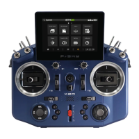
1. For TANDEM X20 as an example,enter into the Model, select RF System, turn on the internal module, select
status [ON] and TD MODE(Type). You can select Internal / External antenna and the power as you need, then
select [Register].
2. Connect the battery to the receiver while holding the button on the receiver. The RED LED and GREEN LED on
the receiver will be on, indicating the [Reg] status.
3. When it shows the Register ID, RX name and UID, click [Register]. The RED LED and GREEN LED on the
receiver will flash, and the transmitter displays [Registration OK ].
4. Turn off the receiver.
5. Move the cursor to select any one of the 3 receivers [Bind].
6. Connect the battery to the receiver.
7. Select the RX, the GREEN will keep lit and the BLUE will flash. Then the transmitter displays [Bind successful].
Specifications
●
Frequency: 2.4GHz & 900MHz
●
Dimension: 53*40*16mm (L*W*H)
●
Weight: 27g
●
Operating Voltage: 4-10v (Recommend 2S Li batteries)
●
Operating Current: ≤185mA@5V
●
Compatibility: Tandem series transmitter & TD protocol capable RF module
●
Dual XT30 Power Input Connector
●
Triple 2.4G/900M Antenna
- 1* Interior 2.4G chip antenna
- 1* External 2.4G antenna (IPEX1)
- 1* Newly designed 900M antenna (Small but with equivalent high-performance as the original 900M antenna)
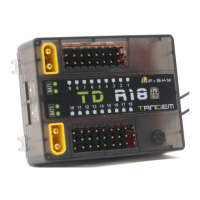
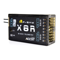
Overview
53mm
9
8 7 6 5 4 3 2
10 11 12 13 14 15 16 17 18
TD R18
1
REG
Button
FBUS
CH9
CH8
CH7
CH6
CH5
CH4
CH3
CH2
CH1
CH10
CH11
CH12
CH13
CH14
CH15
CH16
CH17
CH18
2.4G Antenna
2.4G Antenna
900M Antenna
How to configure channel ports
1. For TANDEM X20 as an example, please select RF System, click [RX1 WD18R]-[Set]-[Options].
2.You will enter into RX Settings,then function definition of every single pin (pin1-pin18) could be set.
- pin1: Smart Port/ SBUS OUT/ FBUS / SBUS In
- pin2-18: Smart Port/ SBUS OUT/ FBUS
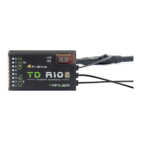
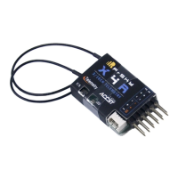
16mm
40mm
Switch UART+AIN
Switch
GND
VIN
S
VO
AIN
GND