G
F
A
C
E
D
B
4 Commissioning
4.2 Delivery status
Upon connecting it up to the 12 V direct current, both LED’s (red and green) light up permanently when in its
ex-works condition, that is to say; no master- or user-fi ngers have been stored in the memory. In this state the
device anticipates that three master-fi ngers for channel 1 and three master-fi ngers for channel 2 shall be tuned in
(for more on this, refer to page 9, chapter 5.1).
4.3 Different radio channels
The transmitter module transmits two different rolling-code encrypted telegrams/channels on 868.3 MHz.
As a result you have the possibility of controlling two different devices:
Channel 1 for the multitronic/autotronic-main entrance door
Channel 2 for another multitronic/autotronic door or, in conjunction with the FUHR radio receiver for a moto-
rised garage door drive unit or e.g. an electrical yard gate.
4.1 Power supply connection
The radio fi ngerprint scanner requires 12 V DC (direct current) operating voltage, collected directly from the
multitronic/autotronic-motor lock’s drive unit.
For more on this, refer also to page 6, chapter 3.2.
Please note!
Please observe the correct polarity (+/-) to the power source!
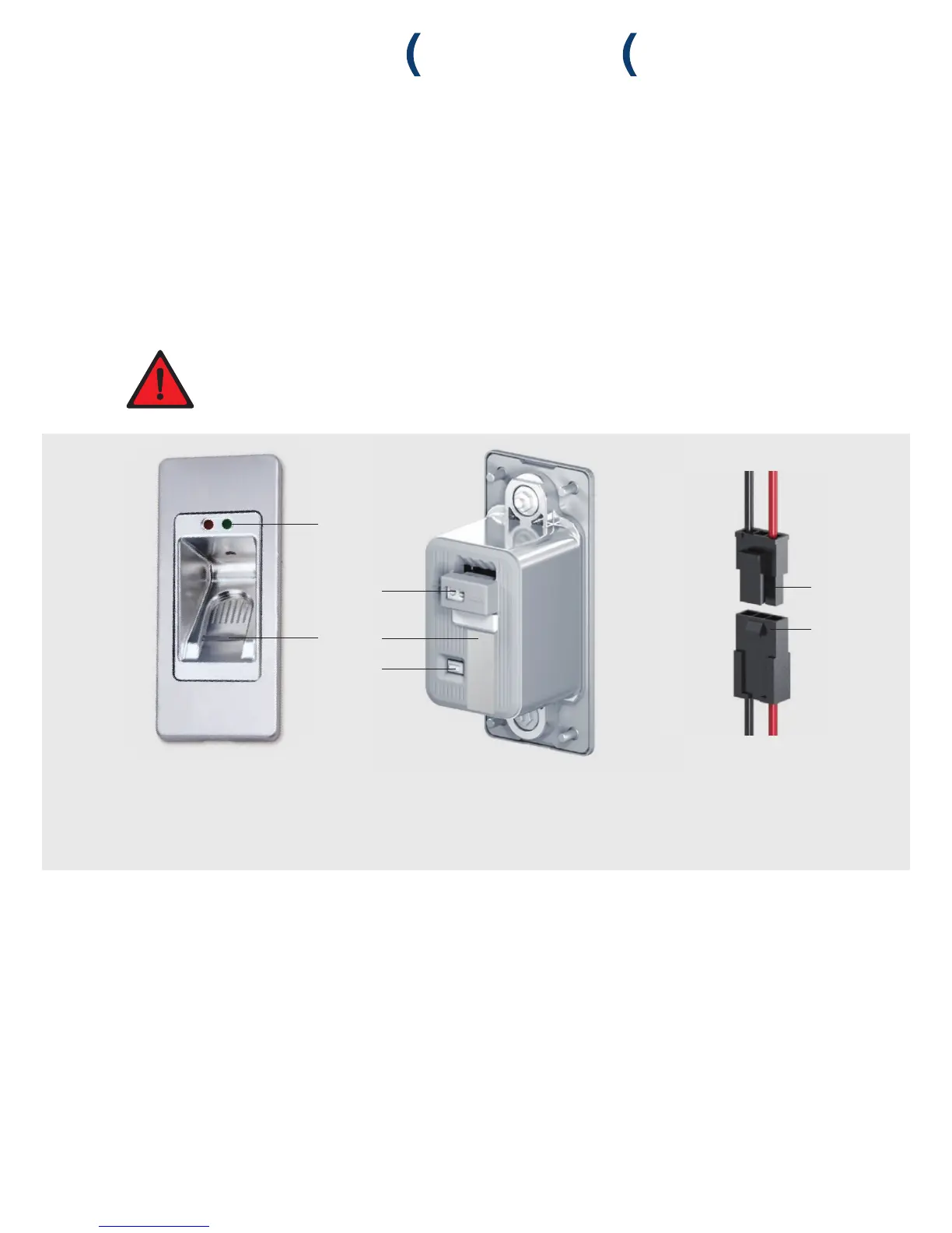
A Active LED’s
B Line-scanner
C Reset button
D Power supply
E Version identifying information (please have this
at hand in the case of service requests)
F Operating voltage connecting cable;
prefi tted to the radio fi ngerprint scanner
G Voltage source connection cable
 Loading...