This document is an application manual for Fuji Electric's SiC Hybrid Modules, V series, specifically the MT5F35778a model, published in November 2021. It provides essential information regarding the use, specifications, and precautions for these power modules.
Function Description:
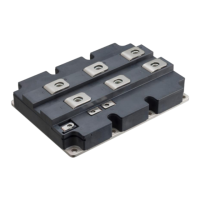
The Fuji Electric SiC Hybrid Module is a power semiconductor device designed for high-efficiency power conversion. It combines the characteristics of Silicon Carbide (SiC) technology with traditional Insulated Gate Bipolar Transistors (IGBTs) to achieve superior performance, particularly in terms of switching speed, power density, and thermal management. The modules are intended for use in various power electronics applications where high voltage and current handling capabilities are required, along with efficient operation. The manual details aspects of its operation, including surge voltage protection, gate resistance selection, parallel connection, electromagnetic interference (EMI) considerations, and methods for suppressing waveform oscillation.
Important Technical Specifications:
- Maximum Junction Temperature (Tvj(op)): The manual specifies a maximum junction temperature of 150°C for all modules of Fuji's 5th generation (U, U4 series). For the 6th generation (V series), this is increased to 175°C. Continuous operation temperature for U and U4 series is around 125°C, while for V series, it is 150°C. These values are based on verification tests conducted according to JEDEC standards.
- Short Circuit (Overcurrent) Protection: The modules are designed with short-circuit withstand times. For a 1700V SiC hybrid module, the short circuit capability (guaranteed short circuit withstand time) and the applied voltage at the time of short circuit occurrence are detailed in Fig. 2-1. The short circuit detection time should be set by referring to this graph.
- Overvoltage Protection and Safe Operation Area (SOA): The manual emphasizes the importance of overvoltage protection during IGBT turn-off and FWD reverse recovery. High dI/dt can cause a high surge voltage due to external wiring stray inductance. The module's maximum rated voltage (VCES) must not be exceeded. Methods to suppress overvoltage include adding a snubber circuit, adjusting the gate resistance (RG), or reducing the inductance of the main circuit. Fig. 2-2, Fig. 2-3, and Fig. 2-4 illustrate the dependence of surge voltage on stray inductance, collector voltage, and current, respectively, at IGBT turn-off. Fig. 2-6 shows the Short Circuit Safe Operating Area (SCSOA) and Reverse Bias Safe Operating Area (RBSOA) for a 1700V SiC hybrid module.
- Gate Resistance (RG) Selection: The selection of gate resistance (RG) is critical. While increasing RG has traditionally been a countermeasure to suppress surge voltage, for 5th generation (U series) and later modules, increasing RG may cause the surge voltage (VCEP) to increase due to improved carrier injection efficiency. Therefore, careful selection of RG is necessary to match the requirements of the actual equipment. Fig. 2-5 and Fig. 2-7 illustrate the gate resistance dependence of surge voltage at IGBT turn-off.
- Parallel Connection: For handling larger output current, modules can be connected in parallel. The manual highlights the importance of current balance.
- Junction Temperature Dependence: The junction temperature dependence of output characteristics has a significant influence on current imbalance. Fig. 2-8 shows typical output characteristics of a 1700V/400A rated module, indicating that the collector current decreases while the junction temperature increases, which can improve current imbalance.
- VCE(sat)/VF Variation and Current Imbalance Ratio: Fig. 2-9 illustrates the relationship between typical variation of VCE(sat)/VF and current imbalance ratio for two parallel-connected modules of V series IGBT and SiC-SBD. The current imbalance ratio increases as the variation of VCE(sat)/VF increases.
- Main Circuit Wiring Inductance Variation: Inhomogeneous main circuit wiring inductance can cause imbalanced current sharing during switching. Fig. 2-11 shows an equivalent circuit for parallel connection. The current sharing is approximately determined by the ratio of main circuit wiring inductance (LC1+LE1 and LC2+LE2). Symmetry of the wiring structure for the collector and emitter sides (Lc1 = Lc2, Le1 = LE2) is crucial. Keeping the main circuit inductance as low as possible is also important to minimize surge voltage during turn-off.
- Gate Drive Circuit: Variations in switching timing due to delay times in separated Gate Driving Units (GDU) can cause current imbalance. Driving all paralleled modules with a single GDU is recommended to reduce switching time variation. However, this may lower switching speed due to insufficient drive capability. Parasitic oscillation can occur during gate voltage rise, so individual gate resistances for each IGBT are recommended (Fig. 2-12). An additional emitter line resistor can help suppress oscillation. Using the auxiliary emitter terminal for gate drive is recommended to suppress transient current imbalance within the module. Shortest possible, equal length, and tightly twisted wires for the gate drive circuit are recommended to reduce mutual induction.
Usage Features:
- Application Manual: This document serves as an application manual, providing guidelines for the proper use and integration of the SiC Hybrid Modules.
- Product Labeling: The module's label includes VCE(sat) and VF values, temperature code, product code, lot number, serial number, and a data matrix code. Combining modules with similar VCE(sat) and VF ranks helps achieve good current balance (Fig. 2-10).
- Waveform Oscillation Suppression: The manual provides a method to suppress waveform oscillation, particularly for the SiC-SBD turn-off waveform. This can be achieved by adding a CR snubber between the collector and emitter of the hybrid module (Fig. 2-14).
Maintenance Features:
-
Handling Precautions (Cautions):
- Transportation and Storage: Shipping carton boxes should be kept upright to prevent stress on terminal pins or inner resin cases. Dropping the product can cause damage. Protection against rain or condensation is necessary to prevent malfunctions. Temperature and humidity during transportation must adhere to the specification sheet.
- Assembly Environment: The power module is highly susceptible to electrostatic discharge (ESD). Suitable ESD countermeasures, as described in the specification sheet, must be implemented in the assembly environment. Removing the conducting pad from control pins makes the product highly vulnerable to electrical damage.
- Operating Environment: The product's performance and appearance cannot be easily ensured if used in environments with acid, organic matter, or corrosive gases (e.g., hydrogen sulfide, sulfurous acid gas).
-
Regular Specification Updates: The contents of the manual are subject to change without notice. Users are advised to obtain the latest specifications when using the product.
-
Intellectual Property: The manual clarifies that no right or license, express or implied, under any patent, copyright, trade secret, or other intellectual property owned by Fuji Electric Co., Ltd. is granted through the use of the applications described. Fuji Electric Co., Ltd. also disclaims any representation or warranty regarding infringement of others' intellectual property rights arising from the use of the described applications.