Do you have a question about the Fujikura FSM–40S and is the answer not in the manual?
This maintenance manual includes safety requirements and guidelines for proper operation.
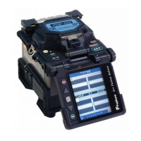
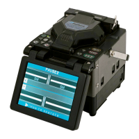
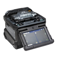
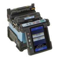
Details the various units that comprise the FSM-40S fusion splicer.
Explains the function of each key and basic operation of the FSM-40S.
Details the necessary cleaning and checks before performing adjustments.
Describes how to access and navigate the secret menu for advanced settings.
Details the factory password required to enter configuration settings.
Procedure for performing an emergency total initialization of all device data.
Instructions for assembling the focus and camera units of the FSM-40S.
Detailed steps for assembling the camera unit, including lens and adapter.
Instructions for assembling the Z-axis unit, comprising Z-clamp and Z-motor units.
Detailed steps for assembling the sheath clamp top component of the Z-axis unit.
Steps for assembling the fiber clamp arm, including shaft and bracket.
Procedure for setting the clamp top, involving gauge blocks and screws.
Steps for installing the focus unit, including attaching the Kyoutou to the focus arm.
Procedure for installing the Z-unit, involving motor unit and liner placement.
Steps for installing the tube heater unit, including fan and wiring.
Instructions for attaching the wind protector and washer to the frame base.
Procedure for attaching the power unit dock to the base frame, including GND wires.
Steps to adjust the set plate position relative to the V-groove using a special tool.
Procedure to adjust Z-clamp height using shims for proper fiber contact.
How to position the fiber clamp correctly over the V-groove center.
Guidance on rough adjustment of the display image for proper fiber visibility.
Steps to adjust camera inclination using the secret menu and set screws.
Detailed procedure for aligning the camera image, including X and Y axis positions.
How to adjust the wind protector mirror angle for optimal image display.
Confirms the camera inclination and parallel position of X and Y axes.
Verifies the movable range of the X and Y swing-arms for proper operation.
Procedure to adjust the tube heater temperature using a thermo spot sensor.
Performs an estimate test to calculate the splicing loss.
Checks the splice quality and displays the result in micrometers.
Calibrates the arc discharge for optimal splicing performance.
Diagram and details of PCB connections for various units and components.
Detailed instructions for replacing the Printed Circuit Board (PCB).
Steps to prepare before replacing the PCB, including config code recording.
Procedure for safely removing the PCB from the unit.
Instructions for installing the new PCB and confirming connections.
How to adjust the voltage indicator sensor for correct battery level display.
Procedure for upgrading software using a programming chip device.
Instructions for upgrading software using an RS-232C cable and PCUG program.
Steps to install the PCUG software required for software upgrades.
Detailed steps for performing the software upgrade using the PCUG program.
Requirements and procedure for downloading data using RS-232C and Excel.
Troubleshooting for error code 01, indicating fiber length issues.
Troubleshooting for error code 02, related to insufficient image brightness.
Troubleshooting for error code 03, caused by dusty fiber or contamination.
Troubleshooting for error code 04, indicating motor overrun conditions.
Troubleshooting for error code 05, relating to the cover being open.
Troubleshooting for error code 06, a variant of cover open detection.
Troubleshooting for error code 07, indicating general motor operational issues.
Troubleshooting for error code 08, when fiber types are mismatched.
Troubleshooting for error code 09, related to arc calibration failures.
Troubleshooting for error code 10, indicating fiber separation after discharge.
Troubleshooting for error code 11, related to improper fiber loading or setting.
Steps to diagnose and resolve issues when the splicer fails to power on.
Diagnosing and resolving issues with the heater not reaching temperature.
A checklist for verifying the display image adjustment procedures.
A comprehensive list of tools required for FSM-40S adjustment procedures.
| Brand | Fujikura |
|---|---|
| Model | FSM–40S |
| Category | Welding System |
| Language | English |