EasyManua.ls Logo

Fujitsu ABYG45LRTA User Manual

Fujitsu ABYG45LRTA
30 pages
To Next Page IconTo Next Page
Page #1 background imageLoading...
Page #1 background image
SPLIT TYPE
AIR CONDITIONER
CEILING TYPE (50Hz)
Indoor unit Outdoor unit
ABYG45LRTA AOYG45LETL
CONTENTS
SPECIFICATIONS . . . . . . . . . . . . . . . . . . .
1
DIMENSIONS. . . . . . . . . . . . . . . . . . . . . . .
2
REFRIGERANT SYSTEM DIAGRAM . . . .
3
CIRCUIT DIAGRAM. . . . . . . . . . . . . . . . . .
4
ERROR DETECTION. . . . . . . . . . . . . . . .
5
INDOOR PCB CIRCUIT DIAGRAM . . . . . .
. . . .
9
OUTDOOR PCB CIRCUIT DIAGRAM
15
PARTS (INDOOR UNIT) . . . . . . . . . . . . .
19
PARTS (OUTDOOR UNIT) . . . . . . . . . . .
24
ACCESSORIES. . . . . . . . . . . . . . . . . . . .
27
www.enindel.com
Question and Answer IconNeed help?

Do you have a question about the Fujitsu ABYG45LRTA and is the answer not in the manual?

Fujitsu ABYG45LRTA Specifications

General IconGeneral
BrandFujitsu
ModelABYG45LRTA
CategoryAir Conditioner
LanguageEnglish

Summary

Fujitsu Split Type Air Conditioner Overview

Technical Specifications and Performance Data

Electrical and Performance Metrics

Covers electrical data, noise levels, compressor, refrigerant, and fan motor specifications.

Physical Dimensions and Weight Details

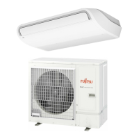
Provides physical dimensions and weight information for indoor and outdoor units.

Unit Dimensions Diagrams

Indoor Unit Physical Layout

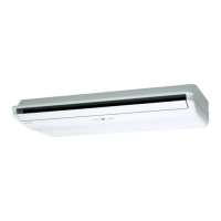
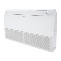
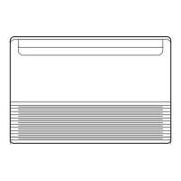
Visual representation of indoor unit physical dimensions.

Outdoor Unit Physical Layout

Visual representation of outdoor unit physical dimensions.

Refrigerant System Schematic

Outdoor Unit Refrigerant Flow

Illustrates refrigerant flow and components within the outdoor unit.

Indoor Unit Refrigerant Flow

Illustrates refrigerant flow and components within the indoor unit.

Electrical Circuit Diagrams

Outdoor Unit Wiring Schematics

Detailed electrical circuit diagrams for the outdoor unit.

Indoor Unit Wiring Schematics

Detailed electrical circuit diagrams for the indoor unit.

Indoor Unit Circuitry and Connections

Control and Power Supply PCBs

Circuit diagrams for the indoor unit's control and power supply PCBs.

Inter-Unit Wiring

Wiring connections between the indoor and outdoor units.

Indoor Unit Main PCB Schematic Details

DC Supply and Power Drive Sections

Focuses on the main PCB's DC supply and power drive circuit areas.

Ancillary Component Circuits

Circuitry for fresh air and heater components on the main PCB.

Indoor Unit Power Supply PCB Schematic

Key PCB Functional Blocks

Diagrams for DC supply, power drive, fan motor, and drain pump connections.

Indoor Unit Indicator PCB Schematic

Indicator to Main PCB Interface

Shows the interface and connections between the indicator and main PCBs.

Outdoor Unit Wiring and PCB Diagrams

Inverter, Filter, and Capacitor PCBs

Circuit diagrams for the inverter, filter, and capacitor PCBs.

Main and Indicator PCBs

Circuit diagrams for the main and indicator PCBs of the outdoor unit.

Outdoor Unit Main PCB Schematic Overview

AC Input and DC Voltage Circuits

Sections related to AC input and DC voltage regulation on the main PCB.

Base Heater Wiring

Specific wiring details for the base heater on the main PCB.

Outdoor Unit Main PCB Detailed Schematic

Outdoor Unit IPM Transistor PCB Schematic

IPM Control and Current Management

Detailed circuit for IPM control and handling reverse current.

Outdoor Unit Power Supply PCB Schematic

External Connection Points

Shows connections from the power supply PCB to the main and indoor unit.

Outdoor Unit Indicator PCB Schematic

Indicator to Capacitor PCB Interface

Details the wiring interface between the indicator and capacitor PCBs.

Error Detection Codes - Indoor Unit

Indoor and Wired Remote Errors

Error codes for indoor unit and wired remote control indicators.

Indoor Unit Display Error Indicators

How errors are visually represented on the indoor unit display.

Remote Control Error Display Format

Format of error display shown on the remote control unit.

Error Detection Codes - Outdoor Unit

Outdoor Indicator PCB LED Error Codes

Error codes indicated by LED patterns on the outdoor unit's indicator PCB.

Outdoor Unit Test Run Procedures

Pre-Test Run Checks and Preparation

Essential checks and preparatory steps before conducting a test run.

Test Run Mode Configuration Steps

Detailed steps for setting cooling or heating test run modes.

Outdoor Unit Pump Down Procedure

Pump Down Preparation Guidelines

Essential preparatory actions required before initiating pump down.

Step-by-Step Pump Down Operation

Comprehensive guide detailing the pump down operation steps.

Indoor Unit Parts Identification

Indoor Unit Drain Pan and Flap Parts

Indoor Unit Fan Motor Parts

Indoor Unit Louver Assembly Parts

Indoor Unit Control Unit Parts

Outdoor Unit Parts Identification

Outdoor Unit Control Box Parts

Outdoor Unit Major Component Parts

Included Accessories

Indoor Unit Accessories List

List of accessories provided for indoor unit installation and operation.

Outdoor Unit Accessories List

List of accessories for outdoor unit piping and installation work.

Optional Parts and Models

Outdoor Unit Optional Parts Catalogue

Catalogue of optional parts for outdoor unit connectivity and functionality.

Related product manuals