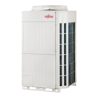
Do you have a question about the Fujitsu AIRSTAGE AJY072LALBH and is the answer not in the manual?
| Brand | Fujitsu |
|---|---|
| Model | AIRSTAGE AJY072LALBH |
| Category | Air Conditioner |
| Language | English |
Precautions for using R410A refrigerant, emphasizing safety and tool requirements.
Lists and describes special tools required for R410A refrigerant handling and installation.
Lists the connecting parts provided with the unit for installation.
Details possible combinations of outdoor and indoor units within a refrigerant system.
Guidelines for choosing a safe and suitable location for outdoor unit installation.
Instructions for proper drainage management from the outdoor unit during operation.
Specifies the required clearance and dimensions for outdoor unit installation.
Details installation space requirements near walls of limited height.
Explains how multiple outdoor units can be connected within a single refrigerant system.
Safe and effective methods for brazing refrigerant pipes, including precautions.
Instructions for connecting refrigerant pipes to indoor units, including separation tubes.
General guidelines and specific steps for piping installation.
Procedures for safely opening knockout holes for pipe entry.
Critical safety warnings and guidelines for performing electrical wiring.
Illustrates typical wiring configurations for outdoor and indoor units.
Proper use of knockout holes for electrical wiring connections.
Guidance on selecting appropriate power supply cables and circuit breakers.
Rules and specifications for installing transmission cables.
Details the type, size, and remarks for transmission cables.
Specifies rules for transmission cable length and network segment connections.
Procedures for enabling and disabling automatic address setting for units.
Step-by-step guide for connecting electrical cables and securing them.
Explains the function and wiring of external input and output terminals.
Diagram showing terminal positions for external inputs and outputs.
Details the purpose and wiring of external input terminals for various functions.
Accessing and identifying PC board switches for unit configuration.
Instructions for setting DIP switches for various functions like unit address and slave count.
How to configure the rotary switch for refrigerant circuit address.
Procedures for setting various functions using push buttons on the outdoor unit PC board.
How to set addresses for signal amplifiers, including automatic and manual methods.
Procedures for setting addresses for indoor units, both manually and automatically.
Step-by-step guide for performing a leak test on the refrigerant piping system.
Method for evacuating the refrigerant system to remove moisture and air.
Procedures and calculations for adding refrigerant to the system.
Detailed steps for charging the system with the correct amount of refrigerant.
Formulas and tables for calculating the total refrigerant amount and additional charge.
Guidelines for installing insulation material on refrigerant pipes to prevent condensation.
A checklist of critical items to verify before performing a test run.
Instructions on how to perform cooling and heating test runs for the system.
Criteria and methods for checking system performance during a test run.
Table of codes indicating normal operating modes of the unit.
List of error codes and their descriptions to help diagnose issues.
Explains the information provided on the unit's label, such as model, serial number, and specifications.



 Loading...