En-11
Function
Function
number
Setting number Default Details
Control
switching
of external
heaters
61
00
Auxiliary
heater con-
trol 1
Sets the control method for the
external heater being used. For
details of the control method,
see the Design & Technical
Manual.
01
Auxiliary
heater con-
trol 2
02
Heat pump
prohibition
control
03
Heater selec-
tion control
using outdoor
temperature 1
04
Heater selec-
tion control
using outdoor
temperature 2
05
Auxiliary
heater control
by outdoor
tempera-
ture 3
06
Auxiliary heat
pump control
07
Auxiliary heat
pump control
by outdoor
tempera-
ture 1
08
Auxiliary heat
pump control
by outdoor
tempera-
ture 2
09
Auxiliary heat
pump control
by outdoor
tempera-
ture 3
Operating
temperature
switching
of external
heaters
62
00 Setting 0
• Sets the temperature condi-
tions when the external heater
is ON.
• For the temperature condi-
tions, see "Temperature condi-
tions when the external heater
is ON". For a more detailed
explanation, see the Design &
Technical Manual.
01 Setting 1
02 Setting 2
03 Setting 3
04 Setting 4
05 Setting 5
06 Setting 6
07 Setting 7
08 Setting 8
09 Setting 9
10 Setting 10
11 Setting 11
12 Setting 12
13 Setting 13
14 Setting 14
15 Setting 15
16 Setting 16
17 Setting 17
Auto mode
type (*3)
68
00
Single
setpoint auto
mode
(traditional)
Switch the setting method of
auto mode to single or dual
(cooling/heating).
For heat pump systems, it is
necessary to set the master
indoor unit (by wired remote
controller).
01
Dual setpoint
auto mode
Deadband
value (*3)
69
00 0°F (0°C)
Choose the minimum tempera-
ture between cooling and heat-
ing settings (deadband) for Dual
setpoint auto mode (set in No.
68).
01 1°F (0.5°C)
02 2°F (1.0°C)
03 3°F (1.5°C)
04 4°F (2.0°C)
05 5°F (2.5°C)
06 6°F (3.0°C)
07 7°F (3.5°C)
08 8°F (4.0°C)
09 9°F (4.5°C)
(Forbidden) 70 00
Standby
time for
auxiliary
equipment
operation
71
00 Disable
Sets the standby time until the
auxiliary equipment operation
starts during primary equipment
operation.
01 1 minutes
02 2 minutes
⁞⁞ ⁞
98 98 minutes
99 99 minutes
Emergency
heat
73
00 Disable
Enables or disable of emer-
gency heat input.
01 Enable
Fan delay
time
74
00 1 minutes
Sets the fan delay time when
the heater is turned off.
01 50 seconds
02 40 seconds
03 30 seconds
External
heater use
in defrost-
ing. (*4)
75
00 Disable
Enables or disables the external
heater use in defrosting.
01 Enable
*1: Auto restart is an emergency function such as for power failure etc.
Do not start and stop the indoor unit by this function in normal operation.
Be sure to operate by the control unit, converter or external input device.
*2: Inappropriate setting may cause an external device malfunction. Confirm whether all
the settings have been performed appropriately according to the installing condition.
*3: Function number 68 and 69 will be usable provided that the corresponding operating
device is connected.
*4: When using function number 75, inappropriate heater selection may cause cold air in
defrosting.
Temperature conditions when the external heater is ON/OFF
Temperature (t) = Room temperature - set temperature
Set value of function: 61
00 01 to 09
ON OFF ON OFF
Set value of function: 62
00 t < -5.4°F (-3°C) t ≥ -1.8°F (-1°C) t ≤ -0.9°F (-0.5°C)
t
≥
+0.9°F (+0.5°C)
01 t < -3.6°F (-2°C) t ≥ -1.8°F (-1°C) t ≤ -1.8°F (-1°C)
t
≥
+0.9°F (+0.5°C)
02 t < -3.6°F (-2°C) t ≥ -1.8°F (-1°C) t ≤ -3.6°F (-2°C)
t
≥
+0.9°F (+0.5°C)
03 t < -5.4°F (-3°C) t ≥ -1.8°F (-1°C) t ≤ -5.4°F (-3°C)
t
≥
+0.9°F (+0.5°C)
04 t < -7.2°F (-4°C) t ≥ -1.8°F (-1°C) t ≤ -7.2°F (-4°C)
t
≥
+0.9°F (+0.5°C)
05 t < -9.0°F (-5°C) t ≥ -1.8°F (-1°C) t ≤ -9.0°F (-5°C)
t
≥
+0.9°F (+0.5°C)
06 t < -5.4°F (-3°C) t ≥ -0.9°F (-0.5°C) t ≤ -0.9°F (-0.5°C) t ≥ 0°F (0°C)
07 t < -3.6°F (-2°C) t ≥ -0.9°F (-0.5°C) t ≤ -1.8°F (-1°C) t ≥ 0°F (0°C)
08 t < -3.6°F (-2°C) t ≥ -0.9°F (-0.5°C) t ≤ -3.6°F (-2°C) t ≥ 0°F (0°C)
09 t < -5.4°F (-3°C) t ≥ -0.9°F (-0.5°C) t ≤ -5.4°F (-3°C) t ≥ 0°F (0°C)
10 t < -7.2°F (-4°C) t ≥ -0.9°F (-0.5°C) t ≤ -7.2°F (-4°C) t ≥ 0°F (0°C)
11 t < -9.0°F (-5°C) t ≥ -0.9°F (-0.5°C) t ≤ -9.0°F (-5°C) t ≥ 0°F (0°C)
12 t < -5.4°F (-3°C) t ≥ 0°F (0°C) t ≤ -0.9°F (-0.5°C) t ≥ -0.9°F (-0.5°C)
13 t < -3.6°F (-2°C) t ≥ 0°F (0°C) t ≤ -1.8°F (-1°C) t ≥ -0.9°F (-0.5°C)
14 t < -3.6°F (-2°C) t ≥ 0°F (0°C) t ≤ -3.6°F (-2°C) t ≥ -0.9°F (-0.5°C)
15 t < -5.4°F (-3°C) t ≥ 0°F (0°C) t ≤ -5.4°F (-3°C) t ≥ -0.9°F (-0.5°C)
16 t < -7.2°F (-4°C) t ≥ 0°F (0°C) t ≤ -7.2°F (-4°C) t ≥ -0.9°F (-0.5°C)
17 t < -9.0°F (-5°C) t ≥ 0°F (0°C) t ≤ -9.0°F (-5°C) t ≥ -0.9°F (-0.5°C)
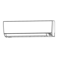
6.3.1 Indoor unit indicator lamps
OPERATION indicator lamp (green)
FILTER indicator lamp (red)
TIMER indicator lamp (orange)
6.3.2 Checking the function settings
Press and hold the “MANUAL AUTO” button on the indoor unit for 3 seconds to check
the function settings. It is necessary to disconnect the power in order to return to normal
operation mode.
(1) Indoor unit and refrigerant address indication
Indication pattern
Indicator name
Indication pattern
Indoor unit address Refrigerant address
OPERATION indicator lamp (Green)
ON Flash (1.0s ON/1.0s OFF)
TIMER indicator lamp (Orange) Address: tens place (0.5s ON/0.5s OFF)
FILTER indicator lamp (Red) Address: ones place (0.5s ON/0.5s OFF)
• Indoor unit address example
(Example) ADDRESS : 24
OPERATION indicator
lamp (Green)
TIMER indicator lamp
(Orange)
FILTER indicator lamp
(Red)
10 sec
1 cycle 12 sec
8 sec
ON
OFF
0.5s
0.5s 0.5s 0.5s
0.5s
0.5s
0.5s 0.5s
0.5s
0.5s
0.5s 0.5s
ON
OFF
ON
OFF
ON
9373370499_IM.indb 119373370499_IM.indb 11 7/28/2020 10:26:22 AM7/28/2020 10:26:22 AM
 Loading...


