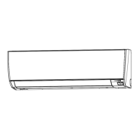
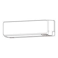
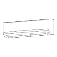
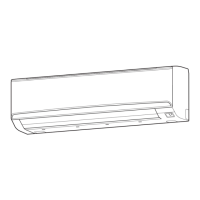
1 START/STOP button
Pressed to start and stop operation.
2 LED lamp
Lights during operation.
3 Operation mode button
Selects the operating mode
4 Set temperature button
Selects the setting temperature.(18-30°C[COOL], 10-30°C[HEAT])
5 Fan control button
Selects the fan speed
6 Louver button
Set the airow direction.
7 Room temperature sensor(inside)
8 Operating mode indicator
(AUTO
*
1, COOL
, DRY
,
FAN *2, HEAT
*3)
.
9 Set temperature
Indicates Indoor unit address. *4
10 Fan speed indicator
(AUTO
, HIGH
, MED
, LOW ,
QUIET
).
11 Airow direction indicator
12 Status icons
Mode mismatch
Filter sign *5
Defrost operation
Oil recovery operation
Under maintenance
Error
Special state
Conducting electricity
Emergency stop
Operation controlled
Forced stop
Remote controller sensor is enabled *5
Central controlled
Setting temperature range is enabled
Operation prohibited
13 Indicates the remote controller address. *4
FUNCTIONS
Display panel
*1 : "AUTO " is not available for a heat pump model unless it is set up as an administrative indoor
unit.
*2 : "FAN " is not available for a heat pump model.
*3 : "HEAT " is not available for a cooling only model.
*4 :
During address display mode.
*5 :
For single split system, to use this function, set the Function setting of the indoor unit accordingly.
4
7
5
3
1
6
2
9
8
10
11
12 13
- (05 - 70) -
CONTROL
SYSTEM
CONTROL
SYSTEM

 Loading...


