En-12
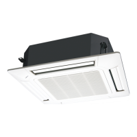
8.3. Attach the intake grille
The installation is the reverse of “REMOVING THE INTAKE GRILLE”.
The intake grille can be rotated and installed 4 ways to suit the user’s preference.
CAUTION
The louver angle cannot be changed if the power is not on, (If moved by hand, it may be
damaged.)
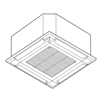
The grille assembly is directional relative to the air conditioner body.
Install so that there is no gap between the grille assembly and the air conditioner body.
9. TEST RUN
9.1. Test run using Outdoor unit (PCB)
• Refer to the Installation Manual for the outdoor unit if the PCB for the outdoor unit is to
be used for the test run.
9.2. Test run using Remote Controller
• Refer to the Installation Manual for the remote controller to perform the test run using the
remote controller.
• When the air conditioner is being test run, the OPERATION and TIMER indicator lamps
flash slowly at the same time.
10. CHECK LIST
Pay special attention to the check items below when installing the indoor unit(s). After
installation is complete, be sure to check the following check items again.
CHECK ITEMS If not performed correctly
CHECK
BOX
Has the indoor unit been installed cor-
rectly?
Vibration, noise, indoor unit
may drop
Has there been a check for gas leaks
(refrigerant pipes)?
No cooling, No heating
Has heat insulation work been completed? Water leakage
Does water drain easily from the indoor
units?
Water leakage
Is the voltage of the power source the
same as that indicated on the label on the
indoor unit?
No operation, heat or burn
damage
Are the wires and pipes all connected
completely?
No operation, heat or burn
damage
Is the indoor unit earthed (grounded)? Short circuit
Is the connection cable the specified
thickness?
No operation, heat or burn
damage
Are the inlets and outlets free of any
obstacles?
No cooling, No heating
Does start and stop air conditioner op-
eration by remote control unit or external
device?
No operation
After installation is completed, has the
proper operation and handling been
explained to the user?
11. ERROR CODES
If you use a wired type remote controller, error codes will appear on the remote controller
display. If you use a wireless remote controller, the lamp on the photodetector unit will
output error codes by way of blinking patterns. See the lamp blinking patterns and error
codes in the table below.
Error indications
Wired remote
controller
error code
Error contents
OPERATION
lamp (green)
TIMER lamp
(orange)
FILTER lamp
(red)
(1) (2)
Remote controller communi-
cation error
(1) (4)
Network communication
error
(1) (6)
Peripheral unit communica-
tion error
(2) (6)
Indoor unit address setting
error
(2) (9)
Connection unit number er-
ror in wired remote controller
system
(3) (1)
Indoor unit power supply
abnormal
(3) (2)
Indoor unit main PCB error
(3) (10)
Indoor unit communication
circuit (wired remote control-
ler) error
(4) (1)
Indoor unit room temp.
thermistor error
(4) (2)
Indoor unit heat ex. temp.
thermistor error
(5) (1)
Indoor unit fan motor 1 error
(5) (2)
Indoor unit coil (expansion
valve) error
(5) (3)
Indoor unit water drain
abnormal
(9) (15)
Outdoor unit miscellaneous
error
(10) (8)
Poor refrigerant circulation
(13) (1)
RB unit error
Display mode
: 0.5 s ON / 0.5 s OFF
: 0.1 s ON / 0.1 s OFF
( ) : Number of flashing
Wired remote controller display
UTY-RLR* (2-wire type)
Error icon
Error icon
Error code
Touch the [Status]. Touch the [Error Information].
For more information, refer to the installation manual of the remote controller.
For more information, refer to the installation manual of the remote controller.
2-digit numbers are corresponding to
the error code in the preceding table.
Touch the [Next Page] (or [previous page])
to switch to other indoor unit information.
UTY-RNR*Z* (2-wire type)
9371022635-01_IM.indb 12 08/02/2019 17:03:36
 Loading...