01-07
Check Item Check contents Judgement Present Status
Number of ref. circuit connected in the network system: ______, Ref. addresses: ______________(00
99)
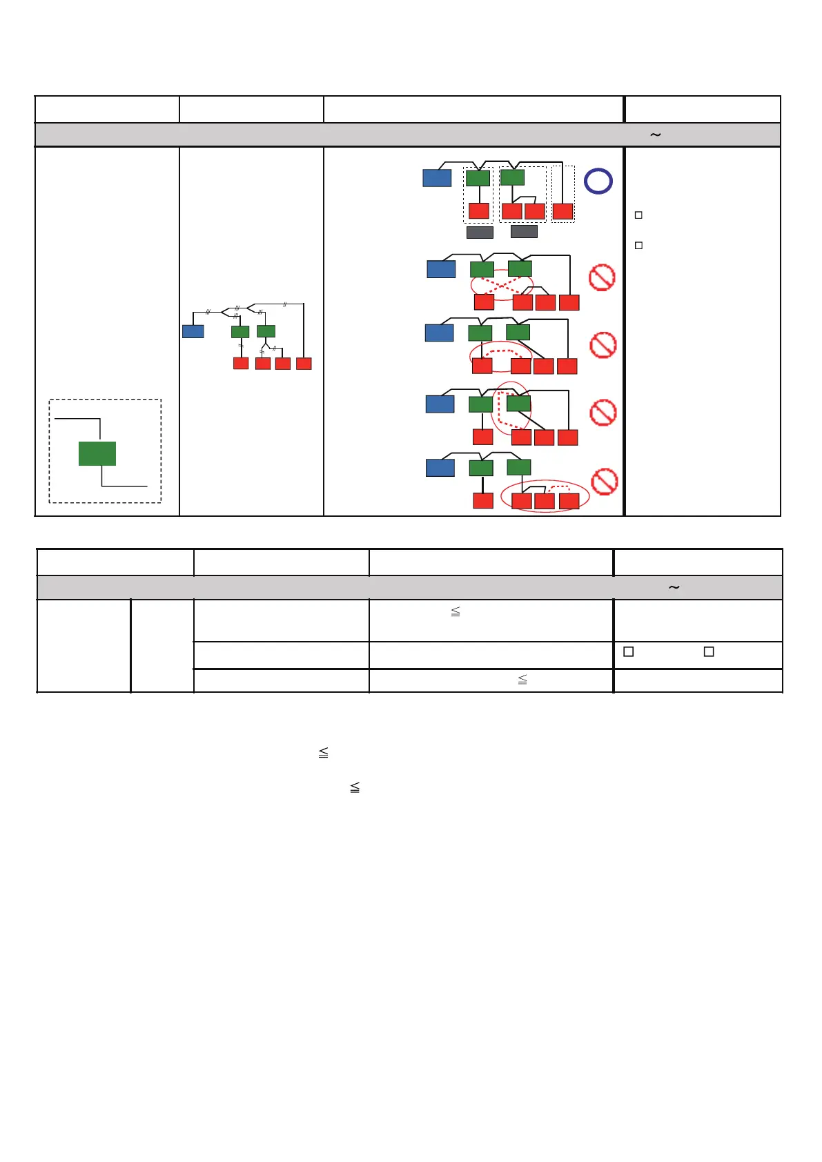
Transmission line
Transmission line layout
(Between RB unit & IU)
Correct
Not correct
If not correct, pls.
rectify the connection
Correct Layout
Not Correct Layout
Example - 1
Not Correct Layout
Example - 2
Not Correct Layout
Example - 3
Not Correct Layout
Example - 4
RB
From outdoor
unit
To indoor
unit
Reference:
Reference:
(Piping Layout)
Check Item Check contents Judgement Present Status
Number of ref. circuit connected in the network system: ______, Ref. addresses:_______________(00 99)
VRF Network
System
Network
wiring
Total transmission line length
Wiring length
11811ft.(3600m)
(Value taken from Network Design Drawing)
(m)
Network wiring layout
Do not make a loop configuration Looped / Notlooped
No. of network segment
( * 1)
No. of network segment 41
( * 1)
Create one Network Segment based on the following conditions,
Condition -1: if the transmission line length 1640ft.(500m)
Condition -2: if a total number of connected units
64 connected units
( * 2)
( * 2)
connected units mean a total of (Indoor Units + Master Outdoor Units + RB Units
( * 3)
+ TPC Units + System Controller Units
Network Convertor f or LonWorks Unit + Central RC Units + Network Convertor Units +
BACnet Gateway Unit + Signal Amplifier Units + Service Tool Unit + Web Monitoring Tool Unit)
( 3)
f or single type RB Unit, count as ‘0’, f or multiple type RB Unit, when all ports are connected with Indoor Unit, count as ‘0’.
However, if one of the port of the multiple type RB Unit is not connected with Indoor Unit, at that time count as one RB Unit.
*
OU
RB
IU
IU
IU
IU
RB
OU
RB
IU
IU
IU
IU
RB
OU
RB
IU
IU
IU
IU
RB
OU
RB
IU
IU
IU
IU
RB
RB Gr.
RB Gr.
OU
RB
IU
IU
IU
IU
RB
OU
RB
IU
IU
RB
IU
IU
1-2-5 Transmission wire installation inspection sheet 2/3
 Loading...