01-08
Check Item Check contents Judgement Present Status
Number of ref. circuit connected in the network system : ______, Ref. addresses :_______ _______________(00
99)
VRF
Network
System
Network
Configuration
No. of IUs & OUs
For one VRF Network System
(IU
400 & OU 100)
IU number : _____
OU number: _____
No. of System Controller
One System Controller per VRF Network System
No. of Touch panel controller (TPC)
Connectable Nos. 16
Total 16 Nos.
Per VRF Network System
(including one Network
Converter for LonWorks)
TPC: _____
No. of Central RC (CRC)
Connectable Nos. 16
CRC: ______
No. of Network Convert for Group RC
Connectable Nos. 64
Group RC: _____
No. of Signal Amplifier (SA) 40
Detail contents:
No. of SA (filter mode OFF) 8
No. of SA (f ilter mode ON ) 32
One per 1640ft.(500m) transmission line length OR,
One per 1312ft.(400m) transmission line length
between units OR,
One per every 64 number of connected units OR,
One per every master OU if total number of
connected Indoor Units
320
Num ber of Signa l
Amplifier :________
No. of Network Convertor ( 100)
One for each separate Room Air- conditioning system Total:_______
No. of BACnet Gateway
One BACnet Gateway per VRF Network System Total: _______
Terminal Register
One per Network Segment (refer to table -9) Total: _______
No. of Network Convertor for LonWorks
One per VRF Network System (IU 128 & OU 100)
NOTE: Special VRF Network system configuration
IU number : _____
OU number: _____
Check Item Check contents Judgement Present Status
Number of ref. circuit connected in the network system : ______, Ref. addresses :_______________________(00
99)
VRF
Network
System
Terminal
Resistance of
transmission
line
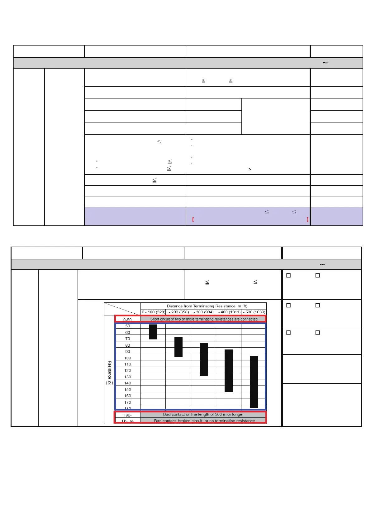
Terminal resistance of transmission line:
From device with connected terminal
resistance (OU or SA) to the most
distance device
50 ohm ( Resistance value) 180 ohm
OK / Not OK
In- between
OU (add____) & SA (add___)
OK / Not OK
In- between
SA (add____) & RB (add___)
OK / Not OK
In- between
OU (add____) & SA (add___)
1-2-5 Transmission wire installation inspection sheet 3/3
 Loading...