Do you have a question about the Fujitsu AJY090LELDHS and is the answer not in the manual?
Important safety and handling notes for R410A refrigerant, including pressure and tool requirements.
Lists and describes the specialized tools required for R410A refrigerant systems.
Guidance on choosing a suitable and safe location for unit installation, considering environmental factors.
Instructions for proper drainage installation to prevent water damage and freezing.
Defines the necessary clearance around the outdoor unit for ventilation, maintenance, and transport.
Safe methods and precautions for lifting, moving, and transporting the outdoor unit.
Detailed steps for securely mounting the outdoor unit on its foundation, including anchoring and vibration reduction.
Guidelines for configuring the system, including pipe length limits and height differences between units.
Specifies correct pipe types, materials, and diameters for R410A systems.
Methods to protect refrigerant pipes from damage during installation and operation.
Procedure for brazing pipe joints using nitrogen gas to prevent oxidation and ensure system integrity.
Instructions for connecting refrigerant pipes to indoor units and branch kits.
Steps for safely opening knockout holes for pipe and cable routing, including panel protection.
Details on connecting refrigerant pipes, including bending, flaring, and using appropriate accessories.
Proper procedures for operating the 3-way valves, including opening and closing methods.
Essential safety guidelines for performing electrical wiring work, including grounding and breaker usage.
Details on opening knockouts and installing protective grommets for electrical wiring.
Guidance on choosing appropriate power supply cables and circuit breakers based on unit specifications and local regulations.
Specifications and rules for transmission wiring, including cable types and maximum lengths.
Connection diagrams and methods for wiring outdoor and indoor units, including power and transmission lines.
Illustrates wiring examples for power supply, transmission lines, and remote controls.
Step-by-step guide for connecting power supply and transmission cables, including torque specifications.
Details on external input/output terminals for functions like low noise mode, emergency stop, and status indication.
Diagrams showing the location of external input/output terminals on the outdoor unit PC board.
Explains the functions and settings for various external input terminals on the unit.
Describes the external output terminals for indicating operation status and error conditions.
Instructions for accessing and setting DIP switches for various unit configurations.
Details the functions and settings of the DIP switches on the outdoor unit PC board.
Procedure for setting the refrigerant system address using the rotary switch.
How to configure unit settings using the push buttons on the PC board.
Configuring energy saving levels to balance performance and efficiency.
Adjusting settings for low noise operation modes to reduce sound output.
Procedure for setting up electricity meter number and pulse input for monitoring.
Methods for setting addresses for signal amplifiers for network communication.
Instructions for setting addresses for indoor units, including automatic and manual methods.
How to measure transmission cable resistance to check for abnormal conditions and ensure proper communication.
Procedure to test refrigerant pipes for leaks using nitrogen gas under pressure.
Steps for evacuating the refrigerant system to remove air and moisture.
Guide to adding refrigerant, including calculation of amounts and proper charging methods.
Instructions for applying thermal insulation to refrigerant pipes to prevent condensation.
Guidance on using putty to seal pipe and wiring holes to prevent pest entry.
Procedure to verify the connection and communication of indoor units before test operation.
Step-by-step instructions for performing the indoor unit connection check.
Explanation of error codes displayed on the 7-segment display and how to interpret them.
Essential checks to perform before starting the test run to ensure proper operation.
Detailed steps for conducting cooling and heating test runs for each refrigerant system.
Codes indicating the normal operating modes of the air conditioning system.
Comprehensive list of error codes and their descriptions for troubleshooting.
Details of the information provided on the unit's label, including model, serial number, and specifications.
| Brand | Fujitsu |
|---|---|
| Model | AJY090LELDHS |
| Category | Air Conditioner |
| Language | English |




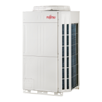

 Loading...