Do you have a question about the Fujitsu AO*24LMAM2 and is the answer not in the manual?
Details about the features of the multi-type 2-room system.
Lists the available indoor and outdoor unit models for the system.
Explains features and operation of wired remote controllers for duct type models.
Details features and operation of wireless remote controllers for other unit types.
Technical specifications for ducted indoor and outdoor units.
Technical specifications for cassette indoor and outdoor units.
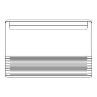
Technical specifications for ceiling indoor and outdoor units.
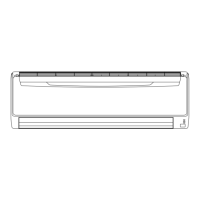
Technical specifications for wall-mounted indoor and outdoor units.
Installation dimensions for ducted indoor units.
Installation dimensions for cassette indoor units.
Installation dimensions for universal indoor units.
Installation dimensions for wall-mounted indoor units.
Wiring diagrams for ducted indoor units.
Wiring diagrams for cassette indoor units.
Wiring diagrams for universal indoor units.
Wiring diagrams for wall-mounted indoor units.
Capacity tables for combinations of indoor and outdoor units.
Performance curves for fan speed and airflow for ducted models.
Airflow patterns for cassette and universal indoor units.
Airflow rates for cassette, universal, and wall-mounted models.
Duct connection diagrams and performance curves.
Noise level graphs for ducted, cassette, universal, and wall-mounted models.
Diagrams showing microphone placement for noise level measurement.
Details on wiring specifications, including cable size and length.
Details on circuit protection mechanisms like fuses and protectors.
Information on thermal protection for fan motors.
Details on thermal protection for compressors.
Information on pressure switch protection for refrigerant circuits.
Optional simple remote controller for duct type models.
Optional remote sensor unit for duct type models.
Optional additional grille for cassette type models.
Optional air purifying filters (Apple Catechin, Wasabi-Ion) for wall-mounted models.
Guidelines for mounting outdoor units considering obstacles.
Diagram of the refrigerant circuit for outdoor units.
Wiring diagrams for outdoor units AO*18L2 and AO*24L2.
Compensation factors for pipe length and height difference for 7000BTU indoor units.
Compensation factors for pipe length and height difference for 9000BTU indoor units.
Compensation factors for pipe length and height difference for 12000BTU indoor units.
Compensation factors for pipe length and height difference for 14000BTU indoor units.
Compensation factors for pipe length and height difference for 18000BTU indoor units.
Calculation method for additional refrigerant charge based on pipe length.
Airflow rates for AO*18L2 outdoor unit (cooling and heating).
Airflow rates for AO*24L2 outdoor unit (cooling and heating).
Noise level graphs for outdoor units AO*18L2 and AO*24L2.
Diagrams showing microphone placement for outdoor unit noise measurement.
Details on wiring specifications for outdoor units, including cable size and length.
Safety devices for circuit protection in outdoor units.
Safety device for fan motor protection in outdoor units.
Safety device for compressor protection in outdoor units.
Safety device for refrigerant circuit protection in outdoor units.
| Brand | Fujitsu |
|---|---|
| Model | AO*24LMAM2 |
| Category | Air Conditioner |
| Language | English |