Do you have a question about the Fujitsu AOYG24LALA and is the answer not in the manual?
Details electrical specifications including voltage, current, power, and E.E.R./COP.
Specifies noise levels for indoor and outdoor units in cooling and heating modes.
Details compressor type, refrigerant type, and charge amount.
Outlines fan speeds for indoor and outdoor units in various operating modes.
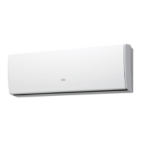
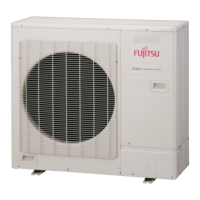
Lists physical dimensions for indoor and outdoor units.
Details the net and shipping weights for indoor and outdoor units.
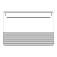
Diagram illustrating the physical dimensions of the indoor unit.
Diagram illustrating the physical dimensions of the outdoor unit.
Diagram showing the refrigerant flow between indoor and outdoor units.
Defines the abbreviations for various thermistors used in the system.
Electrical circuit diagram for the indoor unit, including PCBs and components.
Electrical circuit diagram for the outdoor unit, including PCBs and components.
Diagram of the indoor unit's control unit and power supply PCB.
Schematic for the indoor unit's main PCB and indicator PCB.
Circuit details for DC supply, power drive, and float switch on the main PCB.
Illustrates connections to thermistors, float switch, and remote control.
Circuit diagram for the indoor unit's indicator PCB, showing LEDs and switch connections.
Circuit diagram for the outdoor unit's inverter assembly and main PCB.
Illustrates connections to thermistors, fan motor, and expansion valve.
Circuit diagram showing reactor, power connections, and various component interfaces.
Details error codes and descriptions displayed on the wired remote control.
Provides error codes and descriptions for indoor unit faults.
Parts list for remote control, holder, top cover, and cosmetic panels.
Includes hanger brackets, arms, and associated hardware.
Parts for base assembly, control box, main PCB, and power supply PCB.
Details terminal connectors and room thermistor parts.
Parts include panel, air filter, grill, and support components.
Includes indicator PCB, side cover assembly, and filter bracket.
Components for louver and flap operation, including step motors and links.
Details bushings, louvers, link covers, and motor bases.
Parts include flap base, protect cover, louver stopper, and motor rod.
Details louver parts, support stays, and flap base kits.
Includes separate wall kits, drain pan assembly, drain cap, and hose.
Details the evaporator sub-assembly and pipe thermistor.
Parts for sirocco fan, fan motor assembly, casing, and protectors.
Includes motor fixing table, motor fixture, and barriers.
Parts include protective net, top panel, cabinet, blow down grille, and fan ring.
Details fan motor, reactor assembly, main PCB, and heat sinks.
Includes condenser total assembly, compressor assembly, and compressor thermistor.
Details solenoid coil, 4-way valve, discharge pipe, and expansion valve.
Accessories for mounting include brackets, wall brackets, screws, and nuts.
Includes installation templates, coupler heat insulators, cable ties, and drain hose accessories.
Accessories for the remote control and battery.
Details optional parts for the indoor unit, including wired and simple remote controls.
Specifies accessories for the outdoor unit, such as drain pipes.
| Energy Efficiency Ratio (EER) | 3.21 |
|---|---|
| Refrigerant | R32 |
| Power Supply | 220-240 V, 50 Hz |
| Coefficient of Performance (COP) | 3.61 |
| Type | Split Air Conditioner |