EasyManua.ls Logo

Fujitsu AOY30LMAL User Manual

Fujitsu AOY30LMAL
27 pages
To Next Page IconTo Next Page
Page #1 background imageLoading...
Page #1 background image
SPLIT TYPE
ROOM AIR CONDITIONER
C E IL IN G W A L L
ty pe
CONTENTS
SPECIFICATIONS
. . . . . . . . . . . . . . . . . . . . . . . . . . . . . . . . 1
OUTLINE AND DIMENSIONS . . . . . . . . . . . . . . . . . . . . . . . . . . 3
REFRIGERANT SYSTEM DIAGRAM . . . . . . . . . . . . . . . . . . . . 4
ERROR CONTENTS . . . . . . . . . . . . . . . . . . . . . . . . . . . . . . . . . . 5
CIRCUIT DIAGRAM
. . . . . . . . . . . . . . . . . . . . . . . . . . . . . . .
6
INDOOR PRINTED CIRCUIT BOARD CIRCUIT DIAGRAM . . 7
OUTDOOR PRINTED CIRCUIT BOARD CIRCUIT DIAGRAM 8
DISASSEMBLY ILLUSTRATION . . . . . . . . . . . . . . . . . . . . . . . 12
PARTS LIST . . . . . . . . . . . . . . . . . . . . . . . . . . . . . . . . . . . . . . . 23
STANDARD ACCESSORIES . . . . . . . . . . . . . . . . . . . . . . . . . . . 25
Models Indoor unit Outdoor unit
AWY24LBAJ AOY24LMAL
AWY30LBAJ AOY30LMAL
Question and Answer IconNeed help?

Do you have a question about the Fujitsu AOY30LMAL and is the answer not in the manual?
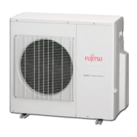
Fujitsu AOY30LMAL Specifications

General IconGeneral
TypeSplit System
Coefficient of Performance (COP)3.61
RefrigerantR410A
Outdoor Unit Dimensions (W x H x D)900 x 830 x 330 mm
Power Supply230 V, 50 Hz, Single Phase
Energy Efficiency Ratio (EER)3.2
Noise Level (Indoor Unit)48 dB(A)

Summary

Specifications

Refrigerant System Diagram

System Flow Diagram

Illustrates the refrigerant flow path between indoor and outdoor units.

Error Contents and Troubleshooting

Error Display Codes

Mapping of error conditions to specific lamp (Operation, Timer, Swing) indicator patterns.

Circuit Diagram

Indoor Unit Circuitry

Detailed electrical circuit diagram for the indoor unit components.

Outdoor Unit Circuitry

Detailed electrical circuit diagram for the outdoor unit components.

Indoor Printed Circuit Board Diagram

Main PCB Layout

Diagram illustrating the main printed circuit board assembly for indoor units.

Outdoor Printed Circuit Board Circuit Diagram

Outdoor Unit PCB Assemblies

Diagrams for inverter, power supply, controller, and TR PCB assemblies of the outdoor unit.

Disassembly Illustrations

Indoor Unit Main Body Components

Exploded view of indoor unit chassis, covers, and main structural parts for disassembly.

Disassembly Illustrations (Outdoor Unit)

Parts List

Indoor Unit Parts

Comprehensive list of part numbers for indoor unit components.

Outdoor Unit Parts

Comprehensive list of part numbers for outdoor unit components.

Related product manuals