Do you have a question about the Fujitsu AOYA30LBTL and is the answer not in the manual?
Details the components included in the package.
Defines key terms used in the manual.
Covers installation and maintenance requirements and regulations.
Procedures for receiving and checking the appliance.
Guidelines for safely moving and handling the unit.
Guidance on choosing the optimal location for installation.
Specific instructions for mounting and positioning the outdoor unit.
Procedures for installing the indoor hydraulic module.
Guidelines for connecting the refrigeration pipes between units.
Steps for vacuum creation and refrigerant gas filling.
Instructions for connecting the heating system to the hydraulic module.
Details on wiring the heat pump system components.
Specific configurations for units with electric backup heating.
Electrical hookups for various heat pump configurations.
Guide to setting system parameters for optimal operation.
Guidance for non-standard installation scenarios.
Shows physical dimensions and connection points for specific models.
Displays physical dimensions and connection details for Model 095.
Dimensions and connection points for larger outdoor units.
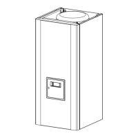
Shows physical dimensions and connection points for the hydraulic unit.
Identifies the parts of the smaller outside units.
Identifies the parts of the Model 095 outside unit.
Identifies the parts of the larger outside units.
Explains how the heat pump transfers energy for heating.
Describes the control functions of the heat pump system.
Outlines safety features and protection mechanisms.
Specific height and fastening requirements for the outdoor unit.
Instructions for installing and managing condensate drainage.
Safety and space requirements for installing the hydraulic module.
Steps for securely mounting and levelling the hydraulic module.
General guidelines and safety measures for refrigeration connections.
Instructions for creating and making flared pipe connections.
Techniques for bending refrigerant pipes without damage.
Step-by-step guide to connecting flared pipes.
Process for creating vacuum and charging refrigerant gas.
Procedure to check for leaks in the refrigeration circuit.
General advice and best practices for hydraulic connections.
Steps to clean the heating system before filling.
Process for filling the circuit with water and removing air.
Information on power supply requirements and safety.
Best practices and warnings for making electrical connections.
Cable sizing and circuit breaker recommendations for the outdoor unit.
Wiring requirements for the heat pump's auxiliary heating system.
How to open the unit to reach the electrical terminals.
Step-by-step guide to connecting wires to terminals.
How to open the hydraulic module's electrical compartment.
Wiring instructions for the hydraulic module.
Connecting the outdoor and hydraulic units.
How to connect the electrical backup heating system.
Connecting external contacts for tariff control.
Connecting external signals to stop the heat pump on fault.
How to install and connect the outdoor temperature sensor.
Connecting optional room thermostats and remote controls.
Steps for commissioning and initial start-up of the heat pump.
Setting up and adjusting room thermostats for heating control.
Initial setup and language selection for the remote control.
Explains the functions of the control panel and remote options.
Details on connecting and using optional room thermostats.
How the system adjusts water temperature based on conditions.
Procedures for manually setting temperature control parameters.
How the system automatically optimizes temperature control.
Overview of user, start-up, and specialist access levels for settings.
Guide to navigating and adjusting system parameters.
Reference for available settings, diagnostics, and status information.
Setting heating schedules for the first circuit.
Setting heating schedules for the second circuit.
Programming domestic hot water production times.
Programming cooling schedules.
Setting heating modes during holiday periods.
Adjusting heating curves and temperature setpoints.
Setting limits for daily heating operation.
Adjusting how ambient temperature affects settings.
Features for drying concrete floors.
Parameters for operating the cooling circuit.
Temperature settings for the second heating circuit.
Further temperature and curve settings for Circuit 2.
Setting up and managing concrete slab drying programs.
Configuring domestic hot water and anti-legionella cycles.
Settings for heating a swimming pool.
Selecting pre-defined installation setups.
Details on DHW tank configurations and related settings.
Tracking maintenance needs and compressor operating hours.
Operating modes for emergency situations and fault conditions.
Testing the functionality of relays in the system.
Verifying the operation of digital outputs.
Checking the status and parameters of heating generators.
Monitoring various system consumers and temperatures.
Instructions for installing and configuring the domestic hot water kit.
Instructions for adding and configuring a second heating circuit.
Guidelines for connecting an external boiler for backup heating.
Information regarding the optional swimming pool heating kit.
Using parameter 5700 to select installation configurations.
Specific connection details for different installation types.
Adjusting system parameters based on the chosen configuration.
Diagram showing the hydraulic piping for configuration 1.
Diagram illustrating the electrical wiring for configuration 1.
Diagram showing the hydraulic piping for configuration 2.
Diagram illustrating the electrical wiring for configuration 2.
Diagram showing the hydraulic piping for configuration 3.
Diagram illustrating the electrical wiring for configuration 3.
Diagram showing the hydraulic piping for configuration 4.
Diagram illustrating the electrical wiring for configuration 4.
Electrical diagram for specific outdoor unit models.
Electrical diagram for the Model 095 outdoor unit.
Electrical diagrams for larger outdoor unit models.
Electrical diagram for the hydraulic module.
Errors indicated on the hydraulic module's digital display.
Faults indicated by flashing diodes on the interface card.
Error codes indicated by diode flashes on specific outside units.
Error codes indicated by diode flashes for Model 095.
Error codes indicated by diode flashes for Models 128 and 155.
Codes displayed for various system data and messages.
| Brand | Fujitsu |
|---|---|
| Model | AOYA30LBTL |
| Category | Air Conditioner |
| Language | English |