EasyManua.ls Logo

Fujitsu AOYA30LFTL User Manual

Fujitsu AOYA30LFTL
29 pages
To Next Page IconTo Next Page
Page #1 background imageLoading...
Page #1 background image
SPLIT TYPE
AIR CONDITIONER
CEILING TYPE (50Hz)
Indoor unit Outdoor unit
ABYA30LBT
ABYA36LBT
AOYA30LFTL
AOYA36LFTL
CONTENTS
SPECIFICATIONS. . . . . . . . . . . . . . . . . . . .1
DIMENSIONS . . . . . . . . . . . . . . . . . . . . . . . 2
REFRIGERANT SYSTEM DIAGRAM. . . . . 4
CIRCUIT DIAGRAM . . . . . . . . . . . . . . . . . . 5
ERROR DETECTION . . . . . . . . . . . . . . . .
6INDOOR PCB CIRCUIT DIAGRAM . . . . . .
. . . .10OUTDOOR PCB CIRCUIT DIAGRAM
15
. . . . . . . . . . . . . .18
PARTS (OUTDOOR UNIT)
PARTS (INDOOR UNIT)
. . . . . . . . . . . .23
ACCESSORIES . . . . . . . . . . . . . . . . . . . . 27
www.enindel.com
Question and Answer IconNeed help?

Do you have a question about the Fujitsu AOYA30LFTL and is the answer not in the manual?

Fujitsu AOYA30LFTL Specifications

General IconGeneral
TypeSplit System
HSPFUp to 9.0
Voltage208/230V
Cooling Capacity30, 000 BTU
Power Supply208/230V, 1 Phase, 60 Hz
Coefficient of Performance (COP)3.5
RefrigerantR410A
Cooling Capacity (BTU)30, 000 BTU
Heating Capacity32, 000 BTU
Noise Level (Outdoor)49 dB

Summary

SPECIFICATIONS

Electrical Data

Detailed electrical specifications for indoor and outdoor units.

Compressor and Refrigerant Details

Information on compressor type, refrigerant, and pipe lengths.

Fan Speed and Noise Levels

Fan speed and noise level data for indoor and outdoor units.

Unit Weight

Weight specifications for indoor and outdoor units.

UNIT DIMENSIONS

Indoor Unit Dimensions Diagram

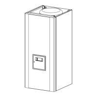
Detailed diagram showing indoor unit dimensions.

Outdoor Unit Dimensions Diagram

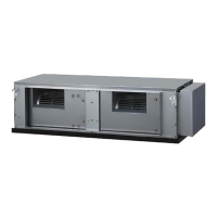
Detailed diagram showing outdoor unit dimensions.

REFRIGERANT SYSTEM DIAGRAM

CIRCUIT DIAGRAMS

Indoor Unit General Circuit Diagram

Overall circuit diagram for the indoor unit.

Indoor PCB Circuit Diagrams

Detailed circuit diagrams for indoor unit PCBs.

Outdoor Unit PCB Circuit Diagrams

Detailed circuit diagrams for outdoor unit PCBs.

ERROR DETECTION

TROUBLESHOOTING AT REMOTE CONTROL LCD

SPECIAL INSTALLATION SETTING

Pump Down Operation

Procedure for collecting refrigerant during unit relocation.

Outdoor Unit LED Error Indicators

Description of errors indicated by outdoor unit LEDs.

PARTS - INDOOR UNIT

Indoor Unit Components

Parts list and diagrams for drain pan and flap.

Louver Assembly Components

Parts list and diagrams for the indoor unit louver assembly.

Fan Motor Assembly Components

Parts list and diagrams for the indoor unit fan motor.

Control Unit Components

Parts list and diagrams for the indoor unit control unit.

PARTS - OUTDOOR UNIT

Outdoor Unit Major Components

Parts list and diagrams for base, condenser, and fan motor.

Outdoor Unit Refrigeration Components

Parts list and diagrams for refrigeration system parts.

Outdoor Unit Electronic Components

Parts list and diagrams for outdoor unit PCBs and electronics.

ACCESSORIES

Related product manuals