En-2
2.3.
For authorized service personnel only.
WARNING
For the air conditioner to operate satisfactorily, install it as outlined in this installation
manual.
Connect the indoor unit and outdoor unit with the air conditioner piping and cables
available from your local distributor. This installation manual describes the correct con-
nections using the installation set available from your local distributor.
Installation work must be performed in accordance with national wiring standards by
authorized personnel only.
Do not turn on the power until all installation work is complete.
CAUTION
This installation manual describes how to install the indoor unit only.
To install the outdoor unit, refer to the installation manual included with the outdoor unit.
• Be careful not to scratch the air conditioner when handling it.
• After installation, explain correct operation to the customer, using the operating manual.
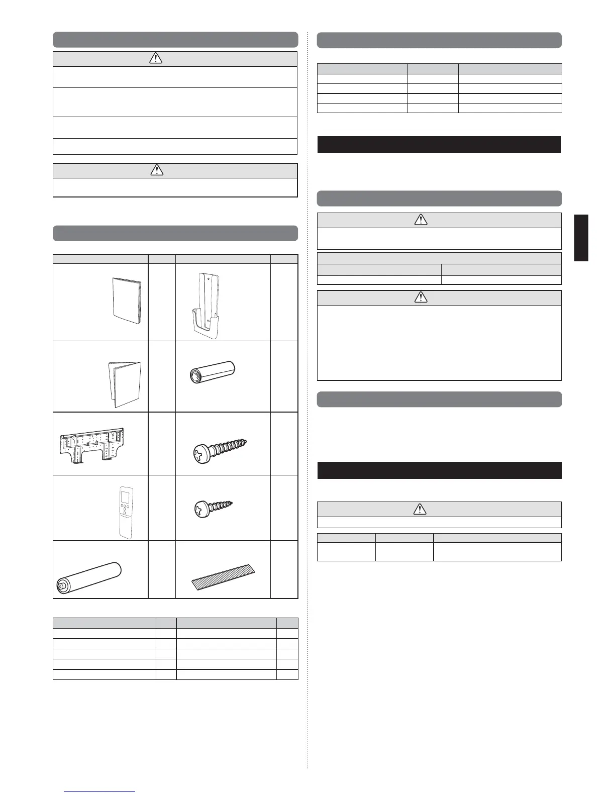
2.4. Accessories
The following installation accessories are supplied. Use them as required.
Name and Shape
Q’ty
Name and Shape
Q’ty
Operating Manual
1
Remote controller holder
1
Installation Manual (This
manual)
1
Cloth tape
1
Wall hook bracket
1
Tapping screw
(M4 × 25 mm)
8
Remote controller
1
Tapping screw
(M3 × 12 mm)
2
Battery
2
Air cleaning filter
2
The following items are necessary to install this air conditioner. (The items are not includ-
ed with the air conditioner and must be purchased separately.)
Name Q’ty Name Q’ty
Connection pipe assembly 1 Wall cap 1
Connection cable (4-conductor)
1 Saddle 1 set
Wall pipe 1 Drain hose 1
Decorative tape 1 Tapping screws 1 set
Vinyl tape 1 Sealant 1
2.5. Optional parts
Refer to each installation manual for the method of installing optional parts.
Parts name Model No. Application
Wired Remote Controller * UTY-RNN¾M For air conditioner operation
Simple Remote Controller * UTY-RSN¾M For air conditioner operation
External connect kit * UTY-XWZX For control input/output port
Communication kit UTY-XCBXZ1 For the installation of optional parts
* Optional communication kit is necessary for the installation.
3. GENERAL
This INSTALLATION MANUAL brieÀ y outlines where and how to install the air conditioning system.
Please read over the entire set of instructions for the indoor and outdoor units and make sure all
accessory parts listed are with the system before beginning.
3.1. Type of copper pipe and insulation material
CAUTION
Refer to the installation manual for the outdoor unit for description of allowable pipe length
and height difference.
Diameter
Liquid pipe Gas pipe
6.35 mm (1/4 in.) 12.7 mm (1/2 in.)
CAUTION
Install heat insulation around both the gas and liquid pipes. Failure to do so may
cause water leaks.
Use heat insulation with heat resistance above 120 °C. Reverse cycle model only)
In addition, if the humidity level at the installation location of the refrigerant piping is
expected to exceed 70%, install heat insulation around the refrigerant piping. If the
expected humidity level is 70-80%, use heat insulation that is 15 mm or thicker and if
the expected humidity exceeds 80%, use heat insulation that is 20 mm or thicker.
If heat insulation is used that is not as thick as speci¿ ed, condensation may form on the surface
of the insulation.
In addition, use heat insulation with heat conductivity of 0.045 W/(m•K) or less 20 °C.
3.2. Additional materials required for installation
A. Refrigeration (armored) tape
B. Insulated staples or clamps for connecting wire (See your local electrical codes.)
C. Putty
D. Refrigeration lubricant
E. Clamps or saddles to secure refrigerant piping
4. ELECTRICAL REQUIREMENT
The indoor unit is powered from the outdoor unit. Do not power indoor unit from separate
power source.
WARNING
Refer to local codes for acceptable cable type.
Cable
Cable size
Remarks
Connection cable
Type 60245 IEC 57
(1.5 mm
2
)
3 cable + Ground, 1 Ø 230 V
Max. Cable Length: Limit voltage drop to less than 2%. Increase cable gauge if voltage
drop is 2% or more.
 Loading...