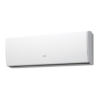
Do you have a question about the Fujitsu AOYG12LLCC and is the answer not in the manual?
Details on power, current, capacity, efficiency, and consumption for cooling and heating.
Fan motor speeds and airflow for indoor and outdoor units.
Information on compressor type, refrigerant, pipe lengths, and charging.
Sound pressure levels for indoor and outdoor units at different fan speeds.
Net and shipping weights for indoor and outdoor units.
Diagrams and measurements for indoor and outdoor unit dimensions.
Diagram illustrating the flow of refrigerant through compressor, heat exchangers, and valves.
Schematic showing connections for indoor unit components like PCBs, fan, and sensors.
Detailed schematic of the indoor unit's Printed Circuit Board (PCB) layout.
Schematic illustrating the outdoor unit's electrical components and connections.
Table listing error codes indicated by operation, timer, and economy lamps.
Mapping of flash patterns to specific error types and potential causes.
Diagram showing exploded view of indoor unit components with part numbers.
Detailed listing of indoor unit parts, including PCBs, thermistors, and covers.
Part numbers for fan motor, crossflow fan, bearing, and casing.
Part numbers for casing, motor covers, louvers, and drain components.
Part numbers for evaporator assembly, pipe joints, and holders.
Diagram showing exploded view of outdoor unit components with part numbers.
Part numbers for reactor, PCB holder, heat sink, and thermistors.
Part numbers for condenser, compressor, solenoid, and expansion valve.
Part numbers for specific outdoor unit models' condenser and compressor assemblies.
List of included accessories such as wall hook bracket, remote control, and screws.
| Brand | Fujitsu |
|---|---|
| Model | AOYG12LLCC |
| Category | Air Conditioner |
| Language | English |


 Loading...